Supercharge Your Innovation With Domain-Expert AI Agents!

Cam target wheel for vehicle

A technology of target wheels and cams, applied in valve details, engine components, machines/engines, etc., can solve problems such as raising manufacturing costs and failing to identify cam vibrations, reducing manufacturing costs and improving operational reliability.

Inactive Publication Date: 2013-04-10
HYUNDAI MOTOR CO LTD
View PDF6 Cites 3 Cited by
  • Summary
  • Abstract
  • Description
  • Claims
  • Application Information

AI Technical Summary

Problems solved by technology

However, since the semicircular cam target wheel 101 in the related art recognizes the phase of the camshaft 110 at equal intervals of 360° on a crank basis, there is a problem that it cannot recognize the cam vibration
However, if a plurality of protrusions 120 are provided, significant changes such as changes in logic development or changes in factory production lines are required, thereby raising manufacturing costs.

Method used


Image

  • Cam target wheel for vehicle
  • Cam target wheel for vehicle
  • Cam target wheel for vehicle

Examples


Embodiment Construction

[0027] Reference will now be made in detail to various embodiments of the invention, examples of which are illustrated in the accompanying drawings and described below. While the invention has been described in conjunction with exemplary embodiments, it will be understood that present description is not intended to limit the invention to those exemplary embodiments. On the contrary, the invention is intended to cover not only the exemplary embodiments, but also various alternatives, modifications, equivalents and others, which may be included within the spirit and scope of the invention as defined by the appended claims. implementation.

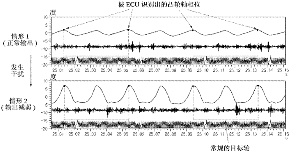
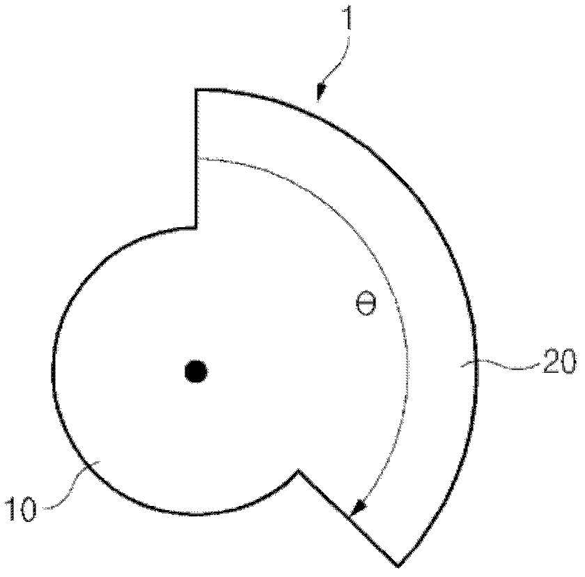
[0028] image 3 is a cross-sectional view showing a cam target wheel for a vehicle according to an exemplary embodiment of the present invention, and Figure 4 is a graph showing an output state of a cam target wheel for a vehicle according to an exemplary embodiment of the present invention.

[0029] Such as image 3 As shown, a cam targ...


PUM


Abstract

A cam target wheel for a vehicle may include a camshaft; and a lobe, formed on an outer circumferential surface of the camshaft, for recognizing a ridge and valley of a cam vibration waveform.

Description

[0001] Cross References to Related Applications [0002] This application claims priority from Korean Patent Application No. 10-2011-0099106 filed with the Korean Intellectual Property Office on Sep. 29, 2011, the entire contents of which are hereby incorporated by reference for all purposes. technical field [0003] The present invention relates to a cam target wheel for a vehicle, and more particularly, to a cam target wheel capable of recognizing vibration of a cam shaft to improve operability of the cam shaft. Background technique [0004] Generally, engines employing continuously variable valve timing (CVVT) have a cam target wheel used to identify cam phase. [0005] Such as figure 1 As shown, the prior art cam target wheel 101 for a vehicle includes a camshaft 110 and a protrusion 120 protruding from an outer circumferential surface of the camshaft 110 at a desired angle θ'. In this case, the angle θ' of the protrusion 120 is 180 degrees. [0006] A conventional ca...

Claims


Application Information

Patent Timeline
Patent Type & Authority Applications(China)
IPC IPC(8): F01L1/08
CPCF01L1/04F01L1/34F01L1/46F01L2820/041F02D35/00F01L1/047
Inventor 赵铭来李洪旭李相禧
Owner HYUNDAI MOTOR CO LTD
Features
  • R&D
  • Intellectual Property
  • Life Sciences
  • Materials
  • Tech Scout
  • Unparalleled Data Quality
  • Higher Quality Content
  • 60% Fewer Hallucinations
Learn More