
Hot plug circuit, interface circuit and electronic equipment assembly

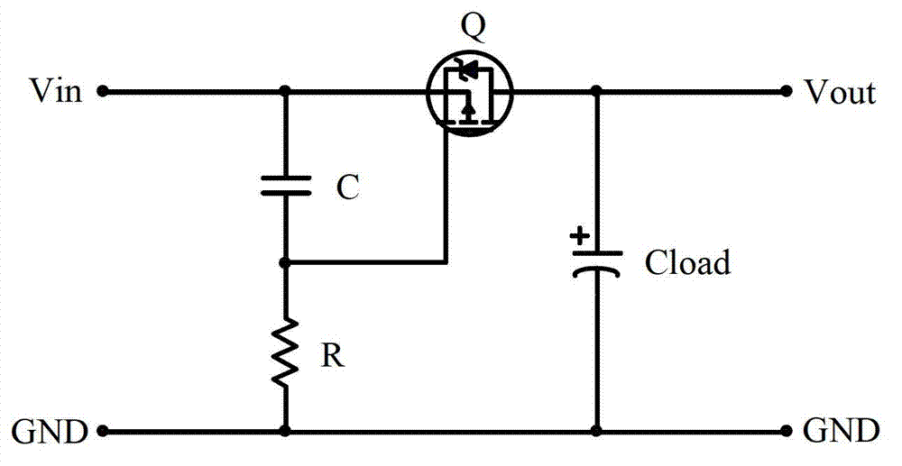
A hot-swapping and circuit technology, which is applied in the electronic field, can solve the problems of not being able to shut down quickly and poor slow-start effect during power-on, and achieve the effect of improving the effect of slow-start

Active Publication Date: 2013-04-10
RUIJIE NETWORKS CO LTD
View PDF6 Cites 11 Cited by
  • Summary
  • Abstract
  • Description
  • Claims
  • Application Information

AI Technical Summary

Problems solved by technology

[0005] Embodiments of the present invention provide a hot-swappable circuit, an interface circuit, and an electronic device component, which are used to solve the problems in the prior art that the hot-swappable circuit has a poor slow start effect when it is powered on, and cannot be shut down quickly when it is powered off.

Method used


Image

  • Hot plug circuit, interface circuit and electronic equipment assembly
  • Hot plug circuit, interface circuit and electronic equipment assembly
  • Hot plug circuit, interface circuit and electronic equipment assembly

Examples


Embodiment 1

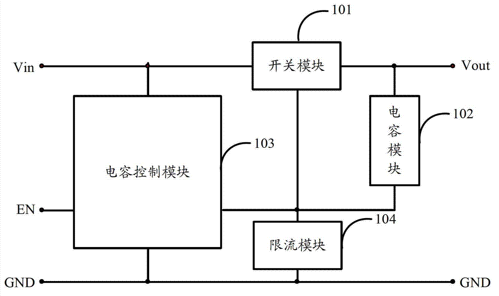
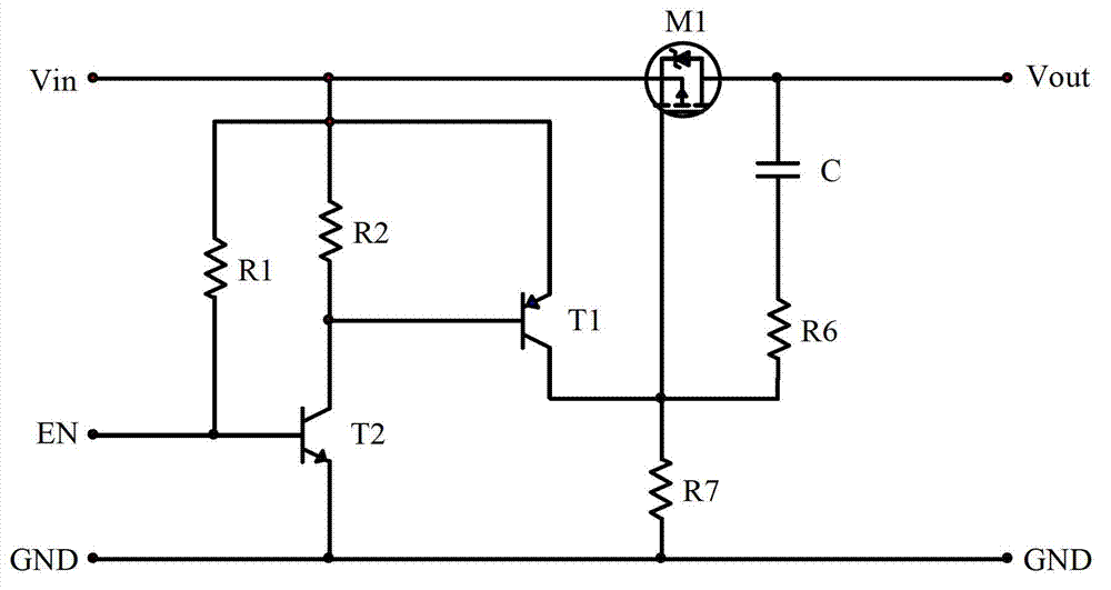
[0028] Embodiment 1 of the present invention provides a positive power supply hot swap circuit, including a switch module 101, a capacitor module 102, a capacitor control module 103 and a current limiting module 104, wherein:

[0029] The first terminal of the switch module 101 is the power input terminal Vin, the second terminal of the switch module 101 is the power output terminal Vout, the third terminal of the switch module 101 and the second terminal of the capacitor module 102, the second terminal of the capacitor control module 103 Four terminals, the first end of the current limiting module 104 are connected; the first end of the capacitor module 102 is the power output terminal Vout; the first end of the capacitor control module 103 is the power input terminal Vin, and the second end of the capacitor control module 102 is the ground terminal GND, the third terminal of the capacitance control module 103 is the enabling terminal EN; the second terminal of the current lim...

Embodiment 2

[0048] Embodiment 2 of the present invention provides a hot swap circuit, including a switch module 101, a capacitor module 102, a capacitor control module 103 and a current limiting module 104, wherein:

[0049] The first terminal of the switch module 101 is the power input terminal Vin, the second terminal of the switch module 101 is the power output terminal Vout, the third terminal of the switch module 101 and the second terminal of the capacitor module 102, the second terminal of the capacitor control module 103 Four terminals, the first end of the current limiting module 104 are connected; the first end of the capacitor module 102 is the power output terminal Vout; the first end of the capacitor control module 103 is the power input terminal Vin, and the second end of the capacitor control module 102 is the ground terminal GND, the third terminal of the capacitance control module 103 is the enabling terminal EN; the second terminal of the current limiting module 104 is th...


PUM


Abstract

The invention discloses a hot plug circuit, an interface circuit and an electronic equipment assembly. The hot plug circuit comprises a switch module, a capacitor module, a capacitor control module and a current limiting module, wherein a first end of the switch module is a power input terminal; a second end of the switch module is a power output terminal; a third end of the switch module is connected with a second end of the capacitor module, a fourth end of the capacitor control module and a first end of the current limiting module; a first end of the capacitor module is a power output terminal; a first end of the capacitor control module is a power input terminal; a second end of the capacitor control module is a grounding terminal; a third end of the capacitor control module is an enabling terminal; and a second end of the current limiting module is a grounding terminal. By using the hot plug circuit provided by the invention, the soft start effect can be improved during electrification and quick cut-off can be realized during power failure.

Description

technical field [0001] The invention relates to the field of electronic technology, in particular to a hot-swappable circuit, an interface circuit and electronic equipment components. Background technique [0002] Hot-swapping means hot-swapping, which allows users to insert and unplug electronic equipment components, such as boards and cards, without cutting off the power supply of the equipment, without causing equipment or peripheral devices to fail, thereby improving the recovery and expansion capabilities of the system wait. [0003] If the load on the component is a capacitive load, without cutting off the power supply of the device, the moment the component is inserted into the device, the sudden connection of the power supply will have a large instantaneous impact on the component, and arc discharge will occur at the connector, and even Cause damage to the equipment; when the component is pulled out, there may be instant contact and instant disconnection at the conn...

Claims


Application Information

Patent Timeline
Patent Type & Authority Applications(China)
IPC IPC(8): G06F13/40
Inventor 杜鹏超迟立华
Owner RUIJIE NETWORKS CO LTD
Learn More