Common mode inductor

A common-mode inductance and magnetic core technology, applied in the field of inductance coils, can solve the problems of loose winding and magnetic flux leakage, and achieve the effects of low cost, high inductance and convenient installation.

Inactive Publication Date: 2013-04-10
孔明
View PDF0 Cites 5 Cited by
  • Summary
  • Abstract
  • Description
  • Claims
  • Application Information

AI Technical Summary

Problems solved by technology

But usually the toroidal coil does not wind a full circle, or the winding is not tight, which will cause the leakage of magnetic flux

Method used


Image

  • Common mode inductor

Examples


Embodiment Construction

[0010] The present invention will now be further described in conjunction with specific examples, and the following examples are intended to illustrate the present invention rather than further limit the present invention.

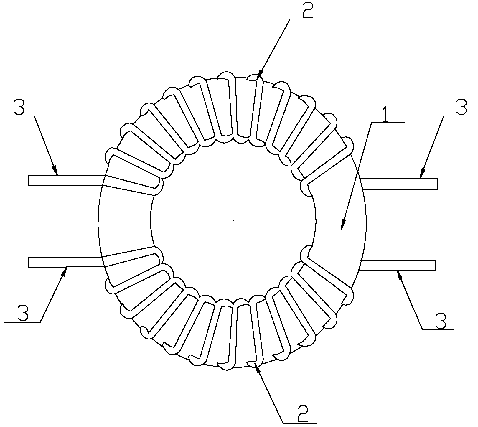
[0011] Such as figure 1 The common mode inductor shown includes a magnetic core 1, two coils 2 wound on the magnetic core 1, and four terminals 3. The two coils 2 have the same size, the same number of turns, and opposite winding directions. The magnetic core 2 It is a ferrite ring magnetic core, and the coil 2 is an insulated wire, which is wound on the magnetic core 1 in a single layer.

[0012] There is an insulating layer between the magnetic core 1 and the coil 2 to prevent breakdown between the two under the action of instantaneous overvoltage.

[0013] During specific implementation, when the normal current in the circuit flows through the common-mode inductor, the current generates a reverse magnetic field in the inductance coil 2 wound in the sam...


PUM


Abstract

The invention relates to an inductance coil, in particular to a common mode inductor. The common mode inductor comprises a magnetic core, two coils and four terminals, wherein the two coils and the four terminals are wound on the magnetic core; the two coils are in the same size and have the same number of turns in opposite winding directions; the magnetic core is a ferrite annular magnetic core; and the coils are insulated conductors, and the coils are wound on the magnetic core in a single layer way. The common mode inductor has the advantages of low cost and convenience in installation and can be wound by a machine with high efficiency. An insulating layer is formed between the magnetic core and the coils, the winding process can be controlled better, and a higher inductance value can be achieved.

Description

technical field [0001] The invention relates to an inductance coil, in particular to a common mode inductance. Background technique [0002] The inductance coil has the characteristic of inhibiting the change of the current. The larger the inductance is, the more obvious this effect is. The effect of this effect on the hindrance of the current is called inductive reactance. The size of the inductive reactance is related to the operating frequency of the inductor and the size of its own inductance. For an ideal inductor model, when the coil is wound, all flux is concentrated in the center of the coil. But in general, the toroidal coil is not wound a full circle, or the winding is not tight, which will cause the leakage of magnetic flux. Common-mode inductors have two windings with a considerable gap between them, which creates flux leakage and creates a differential-mode inductor. A differential mode inductor consists of a coil wound around a core, so when the power flowing...

Claims


Application Information

Patent Timeline
Patent Type & Authority Applications(China)
IPC IPC(8): H01F17/06H01F27/30H01F27/24
Inventor 孔明
Owner 孔明
Why Eureka
Try Eureka