Method for improving safety in assembling battery system and packaged battery system

A technology for assembling batteries and battery systems, applied in battery circuit devices, battery pack components, circuits, etc., can solve problems such as negative impact on battery life, and achieve the effect of eliminating time-consuming, eliminating preparation steps, and eliminating sparks

Inactive Publication Date: 2013-04-10
C TECH UNITED
View PDF4 Cites 0 Cited by
  • Summary
  • Abstract
  • Description
  • Claims
  • Application Information

AI Technical Summary

Problems solved by technology

[0008] · Very high current - negative impact on battery life

Method used


Image

  • Method for improving safety in assembling battery system and packaged battery system
  • Method for improving safety in assembling battery system and packaged battery system
  • Method for improving safety in assembling battery system and packaged battery system

Examples


Embodiment Construction

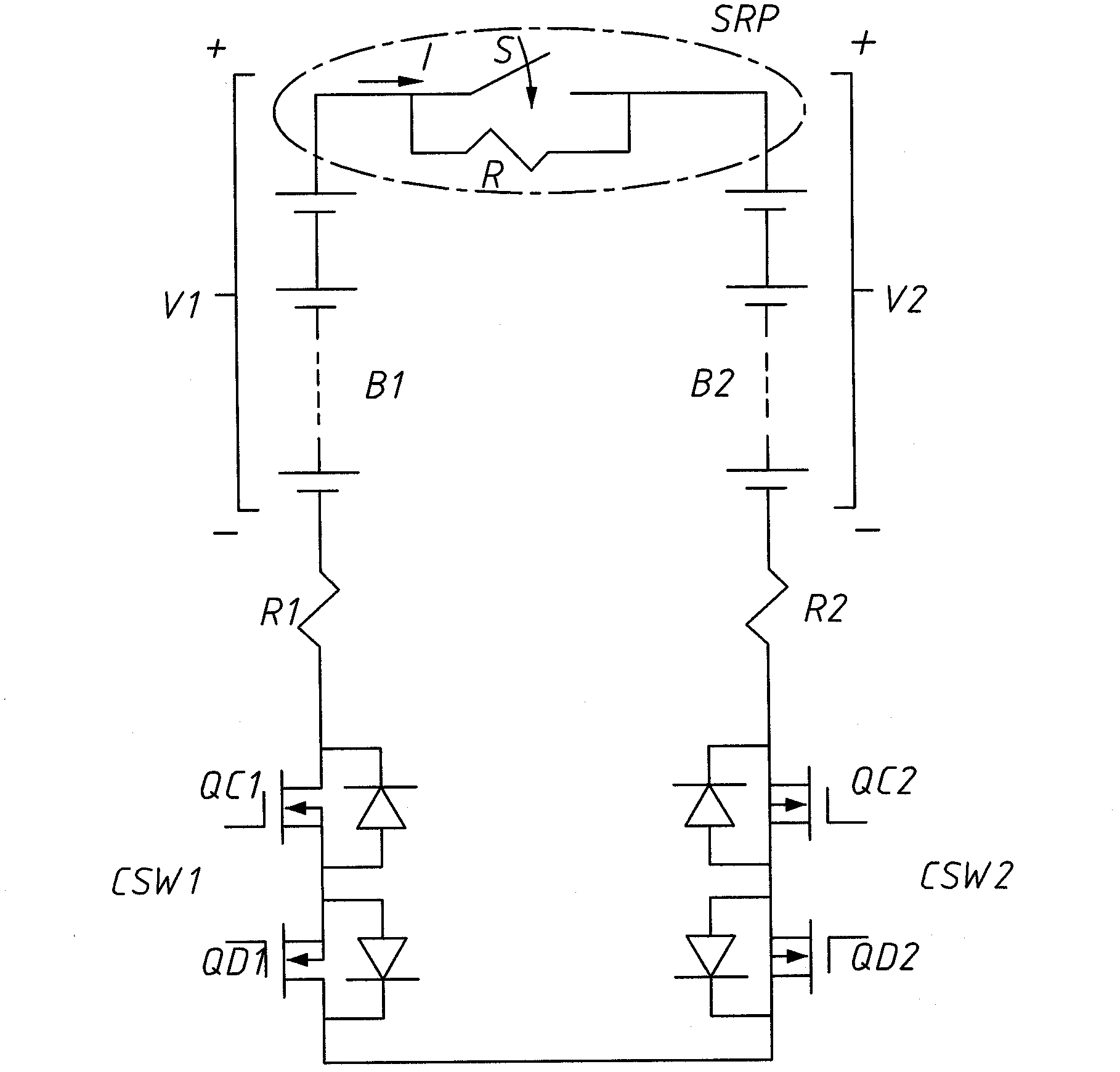
[0039] see figure 2 Solution 1 of the present invention is shown in which a first control switch CSW1 composed of two charging and discharging field effect transistors QC1 and QD1 is connected in series in the first battery branch B1, and a first control switch CSW1 composed of two charge and discharge field effect transistors QC1 and QD1 is connected in series in the second battery branch B2. The second control switch CSW2 composed of the other two charge and discharge field effect transistors QC2 and QD2 is connected to the first battery branch B1 and the second battery branch B2 through a switch-resistor pair SRP.

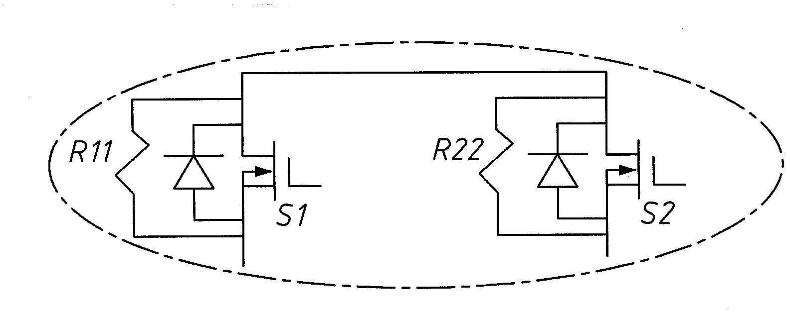
[0040] Solution 1 of the present invention is a simple method to eliminate the arcing effect by using a switch-resistor pair SRP. Switch S in the switch-resistor pair SRP is switched in at a later time when the current level is deemed acceptable. exist image 3 The figure shows that the switch-resistor pair SRP is formed by connecting a first switch S1 compos...


PUM


Abstract

The invention relates to a method for improving safety in assembling a battery system. A first battery branch is connected to a first control switch in series, a second battery branch is connected to a second control switch in series, and a switch-resistor pair is used to connect with the first battery branch and the second battery branch; when the current level is judged to be later than an acceptable time, a switch in the switch-resistor pair is switched on; and the invention provides a packaged battery system for improving the safety.

Description

technical field [0001] The present invention relates to a method for improving safety in an assembled battery system, in particular to a method for using a switch-resistor pair to control the series connection of multiple battery branches to improve safety. Background technique [0002] During the assembly of a battery system, unless special precautions are taken in preparation steps, sparks and large currents may be generated when two battery branches are connected together. Sparks can endanger people, and huge currents can damage battery systems. [0003] exist figure 1 In the circuit shown in , the first battery branch B1 and the second battery branch B2 are connected together via a switch S. The first voltage of the first battery branch B1 is V1 and has a first resistance R1, and the second voltage of the second battery branch B2 is V2 and has a second resistance R2. [0004] When the switch S is cut in, the current I=(V1-V2) / (R1+R2) [0005] For a large battery syst...

Claims


Application Information

Patent Timeline
Patent Type & Authority Applications(China)
IPC IPC(8): H01M2/20H01M2/34H02J7/00
CPCY02E60/10
Inventor 蔡富生
Owner C TECH UNITED
Why Eureka
Try Eureka