Cascade type buck-boost converter input side current control method

A buck-boost converter, boost converter technology, applied in the direction of converting DC power input to DC power output, control/regulation systems, instruments, etc. Filter inductance value and other issues to achieve the effect of reducing system loss

Inactive Publication Date: 2013-04-10
NANJING UNIV OF INFORMATION SCI & TECH
View PDF3 Cites 10 Cited by
  • Summary
  • Abstract
  • Description
  • Claims
  • Application Information

AI Technical Summary

Problems solved by technology

The dual-voltage and dual-current-loop control scheme has the defect that the intermediate stage capacitor voltage must be higher than the output voltage, which increases the voltage stress of the switch tube. The single-voltage loop and dual-current-loop control scheme has the problem of designing three loops. more difficult to design
In the time-sharing operation mode of two switching tubes, the average current control scheme adopted in both the step-up and step-down stages is more suitable for the current control in the step-up stage, but it is not a good choice in the step-down stage. Therefore, in order to ensure The control system is stable, so we have to make more constraints on the hardware circuit parameters, such as increasing the filter inductance value

Method used


Image

  • Cascade type buck-boost converter input side current control method
  • Cascade type buck-boost converter input side current control method
  • Cascade type buck-boost converter input side current control method

Examples


Embodiment Construction

[0029] Below in conjunction with accompanying drawing, the technical scheme of invention is described in detail:

[0030] like figure 1 As shown, the present invention is directed to a cascaded boost-buck converter (the front stage is a boost, and the rear stage is a buck converter) and a cascaded buck-boost converter (the front stage is a buck, and the rear stage is a boost converter), Control its input side current to track the reference current.

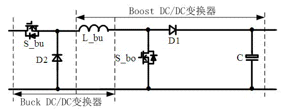
[0031] The implementation method of the present invention will be described below by taking a double-tube cascaded buck-boost converter as an example. Two-tube cascaded buck-boost converter topology such as figure 2 As shown, it can be regarded as a two-stage converter formed by cascading the front-stage buck and the rear-stage boost converter.

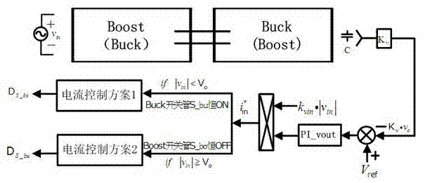
[0032] use as Figure 5 The method shown in the block diagram for controlling the current on the input side of the dual-transistor cascaded buck-boost converter includes the followin...


PUM


Abstract

The invention discloses a cascade type buck-boost converter input side current control method and belongs to the technical field of power electronics. The cascade type buck-boost converter input side current control method can complete control based on comparison between an input voltage and an output voltage of a converter. When the input voltage is lower than the output voltage, a switch tube of a boost converter is constantly conducted, and a first current control scheme is utilized to obtain a conduction duty ratio of the switch tube of the boost converter; and when the input voltage is higher than or equal to the output voltage, a switch tube of a buck converter is constantly cut off, and a second current control scheme is utilized to obtain a conduction duty ratio of the buck converter. The two switch tubes of the cascade type boost converter and the cascade type buck converter can be prevented from simultaneously working in a high-frequency state, system consumption is reduced, effective current control technology can be matched with a voltage boosting stage and a voltage reducing stage, and good input and output performances are achieved.

Description

technical field [0001] The invention discloses a current control method at the input side of a cascaded buck-boost converter, which belongs to the technical field of power electronics. Background technique [0002] In the past 20 years, power electronic technology has developed rapidly, and various power electronic devices have been widely used in chemical industry, communication and other fields. They are divided from the form of electric energy conversion. Such converters include DC-DC (referred to as DC-DC) conversion AC-DC (AC-DC) converters, and DC-AC (DC-AC) converters. If it is divided according to the size relationship between the input and output voltages, it includes step-up type (or called Boost type), step-down type (or called Buck type) and step-up-buck type. Among them, the step-up-buck converter can minimize the difference in sampling values ​​between the input and output voltages, reduce the voltage stress of circuit components and improve system efficiency,...

Claims


Application Information

Patent Timeline
IPC IPC(8): H02M3/155
CPCH02M3/1582
Inventor 毛鹏王伟健
Owner NANJING UNIV OF INFORMATION SCI & TECH
Why Eureka
Try Eureka