Eureka AIR delivers breakthrough ideas for toughest innovation challenges, trusted by R&D personnel around the world.

Anechoic chamber performance measurement system

A microwave anechoic chamber and measurement system technology, which is applied in the field of microwave anechoic chamber performance measurement systems, can solve problems affecting test accuracy, safety hazards, and long time consumption, so as to improve operation stability and measurement accuracy, reduce measurement errors, and improve measurement accuracy. efficiency effect

Active Publication Date: 2013-04-10
CHINA SHIP DEV & DESIGN CENT
View PDF6 Cites 24 Cited by
  • Summary
  • Abstract
  • Description
  • Claims
  • Application Information

AI Technical Summary

Problems solved by technology

The traditional manual measurement of each stroke line not only has a huge workload and takes a long time, but also cannot guarantee the repeatability and accuracy of the measurement. Although the strength of the test bench with metal meets the requirements, it has a large scattering of electromagnetic waves in the anechoic chamber, which affects Test accuracy; adding absorbing materials to the test bench first affects the movement of the test antenna, and in addition, due to the long-term scanning and measurement movement will generate heat, there will be safety hazards (several microwave anechoic chambers in China have caused fires during testing)

Method used


Image

  • Anechoic chamber performance measurement system
  • Anechoic chamber performance measurement system

Examples


Embodiment Construction

[0023] The present invention will be further described below in conjunction with the embodiments and accompanying drawings.

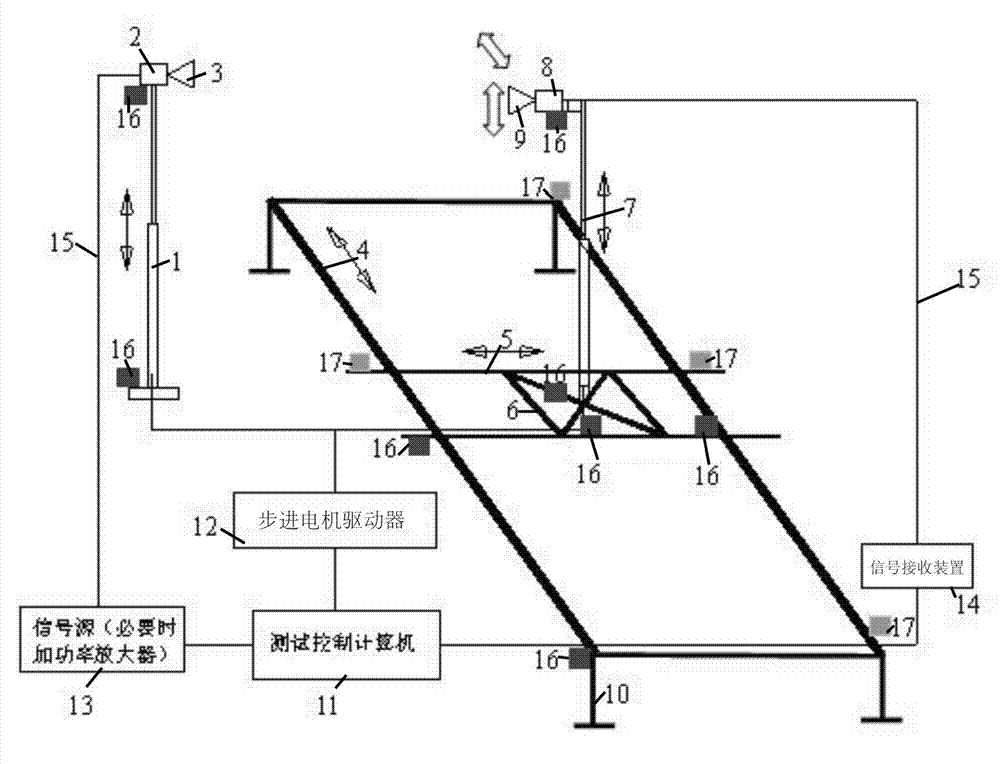
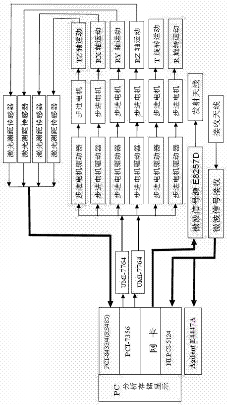
[0024] The microwave anechoic chamber performance measurement system includes test bench and control equipment, figure 1 It is a structural schematic diagram of an embodiment of the present invention, figure 2 It is a control block diagram of an embodiment of the present invention.

[0025] The test bench (in this embodiment, the test bench is made of MC nylon material) includes a transmitting antenna stand for lifting and rotating the transmitting antenna, and a receiving antenna stand for moving and rotating the receiving antenna in three-dimensional space; The transmitting antenna stand is located in the transmitting area of ​​the microwave anechoic chamber, and the receiving antenna stand is located in the quiet zone of the microwave anechoic chamber.

[0026] The control equipment includes a processor 11 (a computer in this embodiment), a laser ...


PUM


Abstract

The invention provides an anechoic chamber performance measurement system which comprises testing racks and control devices. The testing racks comprise a transmitting antenna rack used for lifting and rotating a transmitting antenna, a receiving antenna rack used for moving and rotating the receiving antenna in a three-dimensional space. The control devices comprise a processor, a laser distance measuring sensor, a steeping motor which controls movement of all parts in the testing racks, a signal source and a signal reception device. The anechoic chamber performance measurement system can be applied to measurement of the anechoic chamber along different scanning traces. Automatic measurement of anechoic chamber dead zone reflectivity level, cross polarization character, multipath loss uniformity and field uniformity performance index are achieved by using automatic control, automatic measurement and automatic storage measuring data of a computer. Measurement efficiency is improved, and measurement accuracy is high.

Description

technical field [0001] The invention belongs to the field of electromagnetic compatibility, and in particular relates to a performance measurement system of a microwave darkroom, which is used for measuring performance indexes such as reflectivity level, cross polarization characteristic, multipath loss uniformity and field uniformity in the quiet zone of the microwave darkroom. Background technique [0002] The microwave anechoic chamber is an important experimental site for antenna measurement, electromagnetic compatibility measurement and radar measurement. The performance of the microwave anechoic chamber directly affects the accuracy of various measurements, and it is impossible to correctly evaluate the performance of the equipment. In an ideal microwave anechoic chamber, the reflected energy of electromagnetic waves in the quiet area is zero. In fact, due to the reflection of the absorbing material and walls in the anechoic chamber, part of the sidelobe radiation of t...

Claims


Application Information

Patent Timeline
IPC IPC(8): H04B17/00G01R31/00
Inventor 郑生全黄琼朱传焕蒋炎坤朱涛黄松高
Owner CHINA SHIP DEV & DESIGN CENT
Why Eureka
Eureka Blog
Learn More