Layer mapping and demapping methods and corresponding devices for e-pdcch

A de-mapping and layer-mapping technology, applied in the field of communication, can solve the problems that PDCCH does not support space division multiplexing, does not define PDCCH layer mapping scheme, etc., and achieves the effect of minimizing energy and time and effectively multiplexing

Active Publication Date: 2016-01-20
ALCATEL LUCENT SHANGHAI BELL CO LTD
View PDF3 Cites 0 Cited by
  • Summary
  • Abstract
  • Description
  • Claims
  • Application Information

AI Technical Summary

Problems solved by technology

Since the traditional PDCCH does not support space division multiplexing, in the 3GPP standard Rel-8 / 9 / 10, the layer mapping scheme of PDCCH has not been defined

Method used


Image

  • Layer mapping and demapping methods and corresponding devices for e-pdcch
  • Layer mapping and demapping methods and corresponding devices for e-pdcch
  • Layer mapping and demapping methods and corresponding devices for e-pdcch

Examples


Embodiment Construction

[0017] Embodiments of the present invention are described in detail below with reference to the accompanying drawings.

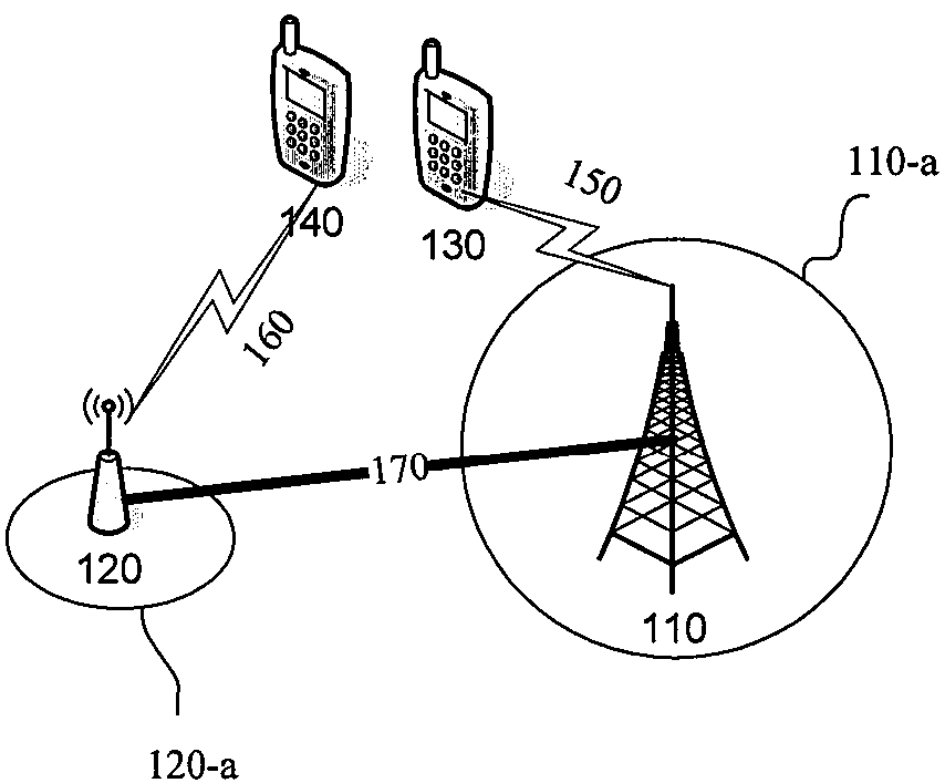
[0018] figure 1 A wireless communication system is shown in which the present invention may be implemented.

[0019] Such as figure 1 As shown, the wireless communication system 100 includes a first base station 110 corresponding to a first cell, a second base station 120 corresponding to a second cell, and user equipments 130 and 140 .

[0020] The first base station 110 provides a first coverage area 110-a and the second base station 120 provides a second coverage area 120-a.

[0021] Here, it is assumed that the user equipment 130 is within the first coverage area 110-a. Accordingly, the user equipment 130 communicates with the first base station 110 via the wireless link 150 . The user equipment 140 is within the second coverage area 120-a. Accordingly, the user equipment 140 communicates with the second base station 120 via the wireless link 160 . ...


PUM


Abstract

The invention discloses a method for layer mapping and demapping of an E-PDCCH and a corresponding device. The method for layer mapping of the E-PDCCH comprises the steps of mapping modulating symbols onto all layers of the E-PDCCH sequentially, so that only when one layer is fully filled with modulating symbols, the rest modulating symbols are mapped to another layer. By the aid of the method and the corresponding device, radio resources can be effectively multiplexed, and the effort and the time consumed for decoding of downlink control information (DCI) expected by user equipment (UE) can be minimized.

Description

technical field [0001] The present invention relates to the field of communication. More specifically, the present invention relates to a method for layer mapping and demapping of an enhanced physical downlink control channel (E-PDCCH) and a corresponding device. Background technique [0002] Designing the enhanced physical downlink control channel E-PDCCH is considered to be an effective method to expand the scheduling capability of the LTE-A system. E-PDCCH supports demodulation based on UE-specific demodulation reference signal (DM-RS) instead of cell-specific reference signal (CRS). Higher flexibility brought about by the deployment of advanced antennas and higher order modulation can be expected in E-PDCCH compared to conventional PDCCH. The E-PDCCH can be realized by enhancing the traditional PDCCH and / or designing a new PDCCH in the data region (that is, the physical downlink shared channel PDSCH). [0003] Similar to traditional PDCCH, E-PDCCH will also adopt repe...

Claims


Application Information

Patent Timeline
Patent Type & Authority Patents(China)
IPC IPC(8): H04W24/02H04W72/04
CPCY02D30/70
Inventor 刘铮蒋琦刘建国杨红卫韩锋沈钢
Owner ALCATEL LUCENT SHANGHAI BELL CO LTD
Why Eureka
Try Eureka