Device for recovering energy

A technology for recovering energy and energy, applied in the direction of accumulator devices, lifting devices, fluid pressure actuating devices, etc., to achieve the effects of simple configuration, reliable operation, and minimized heat loss

Inactive Publication Date: 2013-04-10
HYDAC TECH GMBH
View PDF10 Cites 10 Cited by
  • Summary
  • Abstract
  • Description
  • Claims
  • Application Information

AI Technical Summary

Problems solved by technology

Usually, most of the thermal energy formed when the working gas is compressed is released through the outer walls of the hydraulic accumulators used in the prior art as energy storage systems, and considering the large size of the accumulator housing (preferably steel) surface, the large contact area between the working gas and the outside leads to considerable heat loss

Method used


Image

  • Device for recovering energy
  • Device for recovering energy
  • Device for recovering energy

Examples


Embodiment Construction

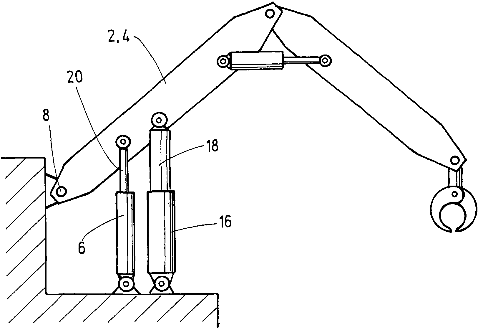
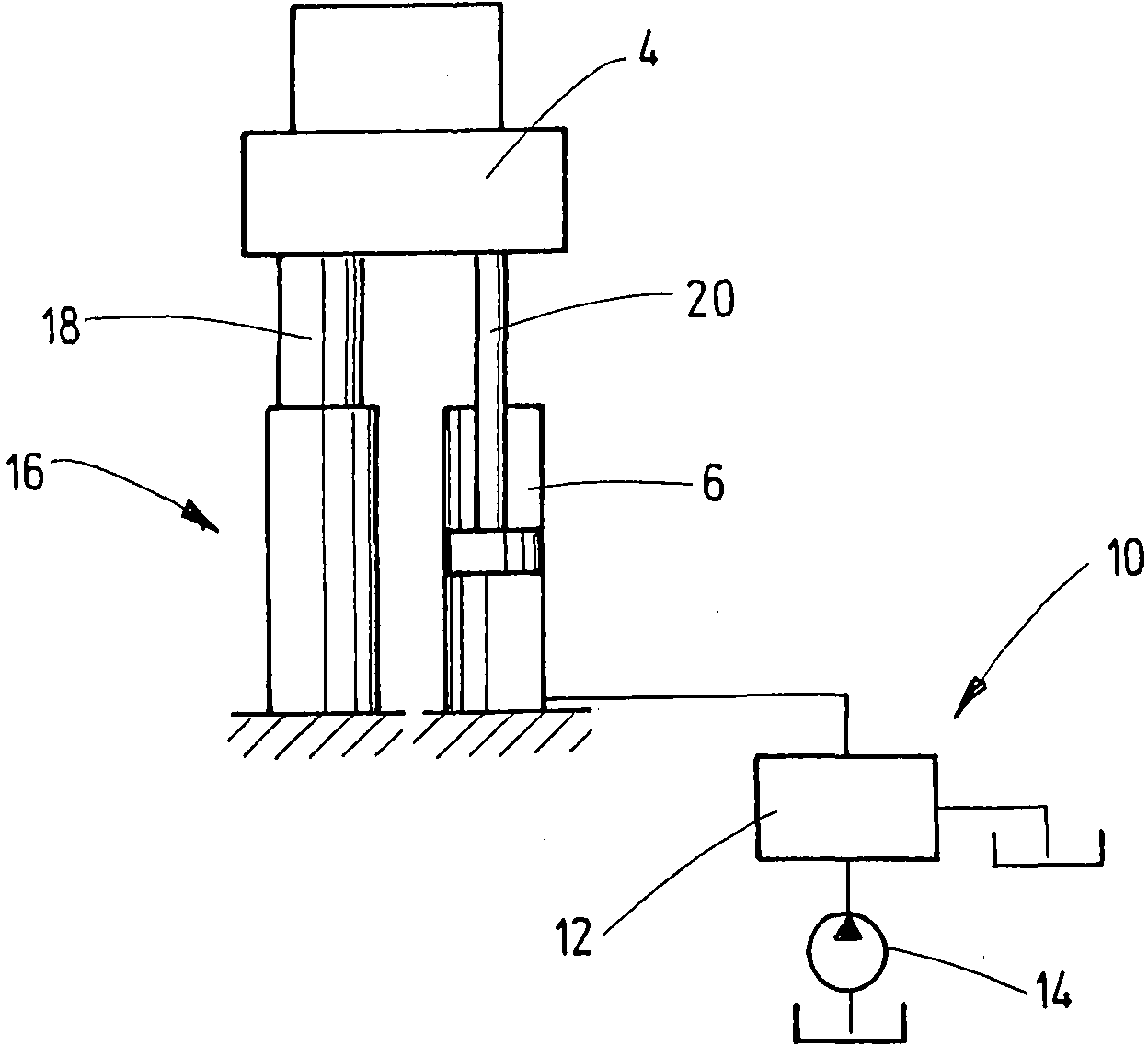
[0024] The invention is described below on the basis of an example embodiment in which a crane boom 2 forms a load block 4 ( figure 2 ). The boom 2 can be raised by means of a power drive in the form of a hydraulic working cylinder 6 ; more specifically, the boom 2 can pivot about a connection point 8 . The working cylinder 6 is a hydraulic cylinder that can be driven by a hydraulic system 10 that is only figure 2 symbolically shown in , see figure 2 , where only the control valve assembly is marked 12 and the hydraulic pump is marked 14. The hydraulic system 10 may, in particular, be of a design commonly used in working machines, and therefore need not be described in detail here.

[0025] The accumulator cylinder 16 is mechanically shunted to the working cylinder 6 forming the power drive; that is, similar to the piston rod 20 of the working cylinder 6, the piston rod 18 of the accumulator cylinder 16 acts directly on the load block 4 (boom 2 )superior.

[0026] im...


PUM


Abstract

The invention relates to a device for recovering energy from work machines, comprising at least one power drive, which can be operated back and forth in order to move a load mass, and an energy store (16), which absorbs energy that is provided when the load mass moves in the one direction and which provides said energy for a subsequent motion in the other direction. Said device is characterized in that an energy store in the form of a storage cylinder (16) is provided, which is mechanically coupled to the load mass and stores pneumatic pressure energy when the load mass moves in the one direction and acts as an auxiliary working cylinder that supports the power drive and that converts the stored pressure energy into driving force when the load mass moves in the other direction.

Description

technical field [0001] The invention relates to a device for recovering energy in a working machine having at least one power drive capable of being driven to move a load mass back and forth and having an energy storage system which absorbs the movement of the load mass in one direction The energy released and made available for subsequent movement in the other direction. Background technique [0002] Devices of this type for recovering potential energy in working machines are prior art; see eg WO 93 / 11363 or EP 0 789 816 B1. As an energy storage system, such devices have a pressure accumulator which stores the released potential energy as pressure energy of the working gas. Generating the lowest possible energy loss in operation is critical to the efficiency of these devices. Said losses mainly consist of losses of thermal energy of the accumulator gas. Usually, most of the thermal energy formed when the working gas is compressed is released through the outer walls of th...

Claims


Application Information

Patent Timeline
Patent Type & Authority Applications(China)
IPC IPC(8): F16F9/00E02F9/22
CPCB66C13/28B66F9/22E02F3/425E02F9/2217F16F9/0236F16F2230/48F15B1/024F15B21/14F16J15/40F16F9/36F16F9/365
Inventor 赫伯特·巴尔特斯弗兰克·鲍尔丹尼尔·菲尔德彼得·克洛夫特
Owner HYDAC TECH GMBH
Why Eureka
Try Eureka