Method for optimizing the energy balance in forming sections in machines for the production of fibrous webs, and forming section

Inactive Publication Date: 2011-02-03
VOITH PATENT GMBH
View PDF41 Cites 4 Cited by
  • Summary
  • Abstract
  • Description
  • Claims
  • Application Information

AI Technical Summary

Benefits of technology

[0021]The inventors recognized that based on the characteristic of the dewatering behavior of the fibrous stock suspension the outgoing dry content at the end of the dewatering unit is not directly proportional to the incoming dry content. Therefore, a greater outgoing dry content in the range of the theoretically achievable maximum dry content that can be reached under line conditions for the specific fibrous stock suspension can be adjusted also with a lower incoming dry content at the dewatering unit. This characteristic is used specifically for energy savings whereby the theoretically available output is not necessarily utilized at all individual dewatering units, but whereby only one of the last, preferably the last dewatering unit in the compression zone is designed and positioned so that it is suitable to achieve a very high or even the maximum drainage capacity under line condition. Therefore, operations occur with a very high or maximum possible energy supply, and therefore a maximum operational capacity, whereby at least one or several upstream dewatering units inside the compression zone are operated in a way that their theoretically achievable outgoing dry content is less than the maximum achievable one at full utilization of the available capacity. Because of this they can be operated with considerable lower energy supply and therefore lower capacity than is necessary to achieve the theoretically possible maximum dry content in conspiring with the last dewatering unit, so that two-digital percentages of air volume savings are possible with dewatering units in the embodiment of suction devices. At the same time the effect of the last dewatering unit inside the compression zone is increased, with the same operationa

Problems solved by technology

Due to the relative movement of the movable wire and the high-vacuum suction device

Method used


Image

  • Method for optimizing the energy balance in forming sections in machines for the production of fibrous webs, and forming section
  • Method for optimizing the energy balance in forming sections in machines for the production of fibrous webs, and forming section
  • Method for optimizing the energy balance in forming sections in machines for the production of fibrous webs, and forming section

Examples


Embodiment Construction

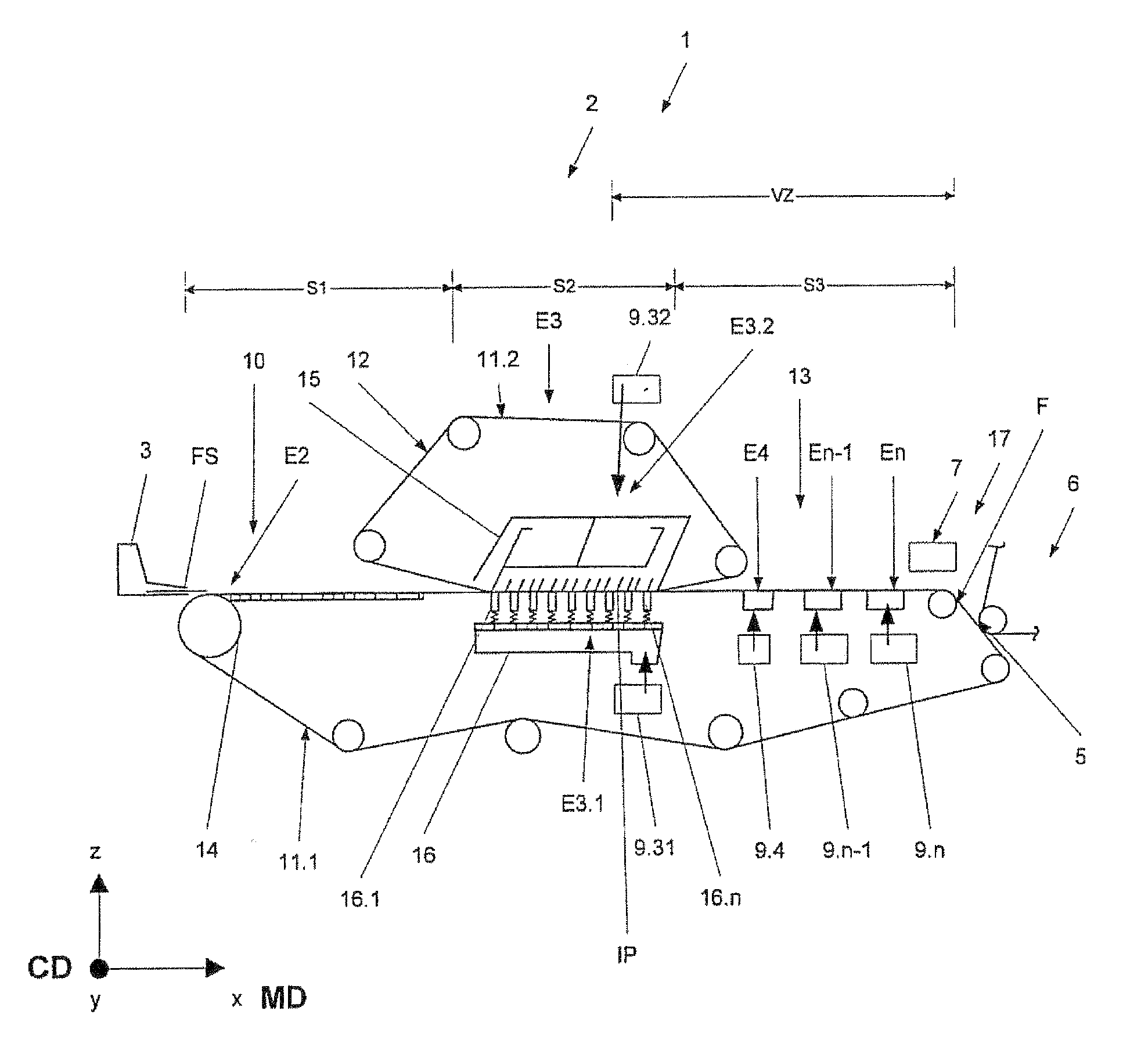
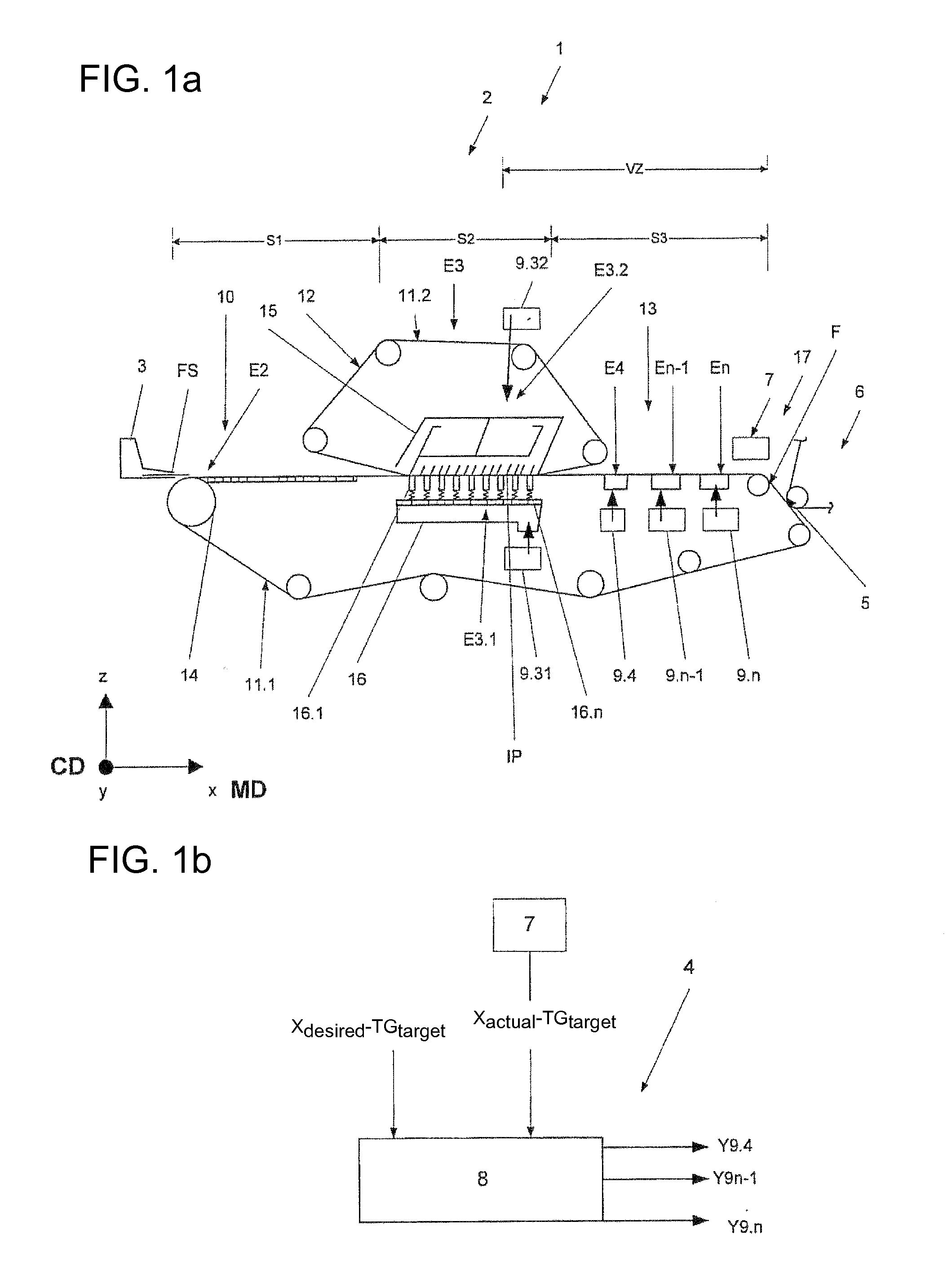
[0046]Referring now to the drawings, and more particularly to FIGS. 1a and 1b, FIGS. 1a and 1b clarify in a strongly simplified schematic view of an example of a forming section 1 and a control / regulating system 4 the basic principle of an inventive method for optimization of the energy balance inside the forming section 1 for a machine 2 for the production of fibrous webs, especially fibrous webs F in the embodiment of paper, cardboard or tissue webs. FIG. 1a shows a strongly simplified schematic of a forming section 1, prior to which a headbox 3 is located through which fibrous stock suspension FS is fed to forming section 1. A coordinate system is attached to forming section 1 for clarification of the individual directions. X-direction describes the direction of travel of the fibrous stock suspension FS and therefore the direction which is also referred to as MD in which the material web which was formed from said suspension travels through machine 2 for the production of fibrous...


PUM


Abstract

The invention relates to a method for optimizing the energy balance of a forming section in a machine for producing fibrous webs, in which a fiber suspension, which is fed to the forming section by way of a material ramp after the immobility point is reached, is passed through at least two dewatering units within a compression zone and to a subsequent functional unit. The invention is characterized in that a setpoint value for a target dryness to be set is predefined based on the existing dewatering elements as a function of a theoretical maximum achievable dryness under plant conditions in the area of the transition zone, said setpoint being selected such that it is less than the theoretical maximum achievable dryness but is equal to or greater than a required minimum dryness in the area of the transition zone, and that the target dryness is controlled by lowering the inlet dryness at one of the last dewatering units disposed in the direction of passage of the fiber suspension within the compression zone.

Description

CROSS REFERENCE TO RELATED APPLICATIONS[0001]This is a continuation of PCT application No. PCT / EP2009 / 059406, entitled “METHOD FOR OPTIMIZING THE ENERGY BALANCE IN FORMING UNITS IN MACHINES FOR PRODUCING FIBROUS WEBS AND FORMING UNIT”, filed Jul. 22, 2009, which is incorporated herein by reference.BACKGROUND OF THE INVENTION[0002]1. Field of the Invention[0003]The invention relates to a method for optimizing the energy balance in a forming section in a machine for the production of a fibrous web, especially a paper, cardboard or tissue web, whereby a fibrous stock suspension which is fed into the forming section through a headbox after having reached the immobility point is passed through at least two dewatering units inside one compression zone following the immobility point, to a transfer area to a following functional unit.[0004]The invention further relates to a forming section, comprising at least one continuous wire supporting the fibrous stock suspension at least indirectly, ...

Claims


Application Information

Patent Timeline
IPC IPC(8): D21F11/00D21F7/00
CPCD21F1/52D21G9/0027D21F9/003D21F3/10
Inventor RUEHL, THOMASSCHMALENBACH, MORITZSCHMIDT-ROHR, VOLKERESPER, MARCOKAUFMANN, OLIVER
Owner VOITH PATENT GMBH
Why Eureka
Try Eureka