Integrated finish machining method for inner profile and corner of pocket

A technology of groove features and corners, applied in the field of machining of mechanical parts, can solve the problems of tool chipping, uneven force on the tool, tool vibration, etc., to improve processing efficiency, improve processing quality, and avoid tool marks.

Active Publication Date: 2013-04-17
NANJING UNIV OF AERONAUTICS & ASTRONAUTICS
View PDF9 Cites 16 Cited by
  • Summary
  • Abstract
  • Description
  • Claims
  • Application Information

AI Technical Summary

Problems solved by technology

[0007] The purpose of the present invention is to solve the problems of low efficiency, low machining quality of the surface of the workpiece, and uneven stress on the tool during the machining process, resulting in vibration of the tool, which easily causes accidents such as chipping and breaking of the tool. In order to solve such problems, an integrated machining method for internal corners of groove features with high efficiency, high surface processing quality and stable tool load was invented.

Method used


Image

  • Integrated finish machining method for inner profile and corner of pocket
  • Integrated finish machining method for inner profile and corner of pocket
  • Integrated finish machining method for inner profile and corner of pocket

Examples


Embodiment Construction

[0045] The present invention will be further described below in conjunction with the drawings and embodiments.

[0046] Such as Figure 1-6 Shown.

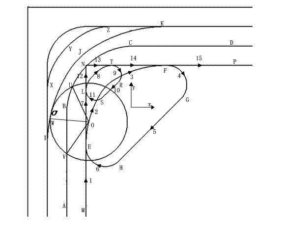
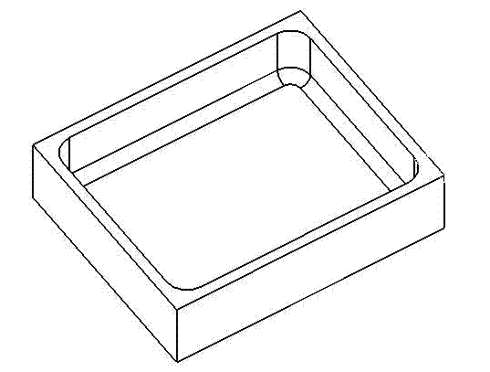
[0047] Attached figure 2 with image 3 It is a schematic diagram of the groove characteristics and processing paths of typical aircraft structural parts, as detailed below.

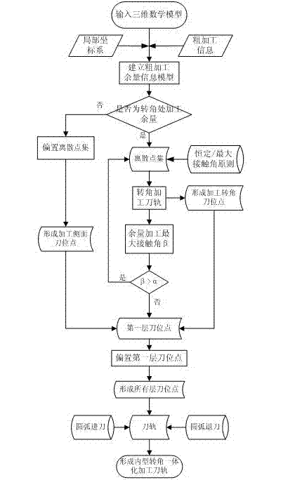
[0048] An integrated finishing method for the inner corner of the groove feature, it should first use the existing technology to image 3 The three-dimensional mathematical model of the part shown is input into the computer and the rough machining process NC program is generated according to the existing machining process, and then the generated rough machining process program is stored in the computer for calling, this embodiment and all of the present invention The starting point is all under the premise that the rough machining process information has been generated. The integrated processing steps of the entire inner shape and corner are (such as figure 1 Show...


PUM


Abstract

The invention discloses an integrated finish machining method for an inner profile and a corner of a pocket. The integrated finish machining method comprises the steps that a rough machining allowance curvilinear equation is established according to rough machining information of the pocket; then a rough machining allowance curve is discretized; a discrete point of a side face allowance equation is subjected to outward normal bias to form a cutter location point of a machining side face; circular machining is conducted at the corner by using the discrete point at the corner and the side face allowance curvilinear equation according to a constant contact angle and maximum contact angle principle; the cutter location point of the corner is solved; an axial first cutter location point layer is further formed; the first cutter location point layer is subjected to axial cutting-in and bias layer by layer in the reverse-axial direction of a cutter till a last layer; all the cutter location points are obtained; a cutter advancing and retreating arc is set; and all the cutter location points are connected to form an integral cutter track of the integrated machining method for the inner profile and the corner of the pocket. With the adoption of the method, cutter changing is avoided; the machining quality of a workpiece surface is improved; the effect of a contact angle on stress of the cutter is taken into account; the constant contact angle and maximum contact angle principle is provided; the vibration of the cutter is reduced; and the service life of the cutter is prolonged.

Description

Technical field [0001] The invention relates to a machining method of mechanical parts, in particular to a finishing method of the groove inner profile and its corners, in particular to a method for integrating the groove characteristics inner profile and corners on a CNC milling machine using the same tool Methods of finishing. Background technique [0002] Groove features are widely present in aircraft structural parts. At present, the machining method adopted by aviation OEMs is to first finish the inner profile with a large-diameter tool, and then use a small-diameter tool to finish the corner. This method needs to change the tool during the machining process, which affects the machining efficiency; due to the sharp change in the cutting force when machining the corner, the vibration of the tool is increased, the wear is accelerated, and accidents such as tool chipping and tool breakage may occur; in addition, due to tool change The reason is that there will be obvious cutti...

Claims


Application Information

Patent Timeline
Patent Type & Authority Applications(China)
IPC IPC(8): B23C3/00
Inventor 李迎光刘长青高鑫郝小忠刘旭王伟李海
Owner NANJING UNIV OF AERONAUTICS & ASTRONAUTICS
Why Eureka
Try Eureka