
Die-cutting roller circumference aligning device

A technology of alignment device and die-cutting roll, applied in metal processing and other directions, can solve the problems of complex, complex structure and large adjustable range.

Active Publication Date: 2013-04-17
坂崎雕刻模具(昆山)有限公司
View PDF5 Cites 3 Cited by
  • Summary
  • Abstract
  • Description
  • Claims
  • Application Information

AI Technical Summary

Problems solved by technology

[0005] Traditional adjustable gears generally use gear regulators and other devices, which occupy a large space, have a complex structure, and have a relatively large adjustable range. However, when used on a die-cutting machine, the adjustment range only needs 1-1.5 teeth. Die-cutting machines usually There is not enough space, too complicated and inconvenient to align the upper and lower rollers in the circumferential direction before mass production, which affects production

Method used


Image

  • Die-cutting roller circumference aligning device
  • Die-cutting roller circumference aligning device

Examples


Embodiment Construction

[0022] The present invention will be further described below in conjunction with the accompanying drawings and specific embodiments.

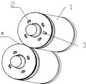
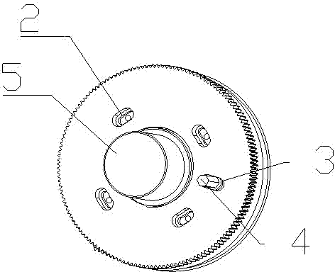
[0023] according to Figure 1-2 , the die-cutting roller circumferential alignment device, including the upper and lower rollers 1, the shoulder 5 located at the end of the roller 1, is characterized in that: it also includes an adjustable gear 6 fixed on the side of the upper roller; the adjustable gear 6 is provided with a sinker fixed The waist-shaped hole 2 of the screw and the adjustment hole 3 of the eccentric adjustment block 4 are arranged. The waist hole 2 is a quadrilateral with two opposite sides extending outwards (such as figure 2 ), rectangle or polygon. The adjustment hole 3 is quadrilateral, rectangular or polygonal in shape with two opposite sides extending outward. The circumferential alignment device of the die-cutting roller also includes a gear fixed on the side of the lower roller; the gear is provided with four waist-...


PUM


Abstract

The invention belongs to the field of machining of a carving mould, and particularly relates to a die-cutting roller circumference aligning device. The die-cutting roller circumference aligning device comprises upper and lower rollers, and shaft shoulders located at the end parts of the knife rollers. The die-cutting roller circumference aligning device is characterized by further comprising an adjustable gear fixed on the lateral face of the upper roller; and a kidney-shaped hole of a counter-sunk fixing screw and an adjusting hole for arranging an eccentric adjusting block are arranged on the adjustable gear. According to the die-cutting roller circumference aligning device provided by the invention, the adjustable gear is mounted on the upper roller; and the lower roller is provided with an ordinary gear. The kidney-shaped hole is formed in the adjustable gear, and a space is adjusted in a circumference direction when the displacements of the gear and the rollers are adjusted. An adjusting block is manually adjusted by using a hexagon wrench, and the circumference directions of the gear and the rollers are displaced through the eccentricity of the adjusting block, so that the adjustment effect can be realized. The die-cutting roller circumference aligning device is convenient and practical, has low cost, can be used for aligning the circumference directions of the upper and lower rollers in a die-cutting manner, and ensures die-cutting precision and quality.

Description

technical field [0001] The invention belongs to the field of engraving mold processing, in particular to a peripheral alignment device for die-cutting rollers. [0002] Background technique [0003] The working parts of the plate table and the press-cutting mechanism of the rotary die-cutting machine are cylindrical. When working, the paper feed roller sends the cardboard between the mold plate cylinder and the pressure cylinder, and the two clamp it. The cylinder is used for die-cutting, and the die-cutting plate cylinder rotates once to complete a working cycle. [0004] In the die-cutting industry, the upper and lower rollers require high matching precision and the upper and lower matching of the creasing rollers. If the alignment in the circumferential direction is not accurate, the produced products will be waste products, waste materials, increase costs, and are easy to be damaged. Die-cutting rollers, affecting production. It is difficult to align the upper and low...

Claims


Application Information

Patent Timeline
Patent Type & Authority Applications(China)
IPC IPC(8): B26D7/26B26F1/42
Inventor 王建庚
Owner 坂崎雕刻模具(昆山)有限公司
Learn More