Eureka AIR delivers breakthrough ideas for toughest innovation challenges, trusted by R&D personnel around the world.

Injection molding machine for material separation injection molding

A technology of injection molding machine and material distributing mechanism, which is applied in the field of injection molding machines, can solve the problems of low work efficiency and low work efficiency of injection molding mechanism, and achieve the effects of improving pass rate, reducing waiting time, and ensuring uniformity

Inactive Publication Date: 2013-04-17
宁波赫仕机械制造有限公司
View PDF5 Cites 2 Cited by
  • Summary
  • Abstract
  • Description
  • Claims
  • Application Information

AI Technical Summary

Problems solved by technology

[0002] Since a working cycle of the injection molding machine includes several processes, and the existing injection molding machine only performs one injection in a working cycle, the working efficiency of the injection molding mechanism is low
Especially electric injection molding machines are generally driven by expensive servo motors, and the servo motors spend most of their time waiting for other processes to be completed, resulting in low work efficiency

Method used


Image

  • Injection molding machine for material separation injection molding
  • Injection molding machine for material separation injection molding
  • Injection molding machine for material separation injection molding

Examples


Embodiment Construction

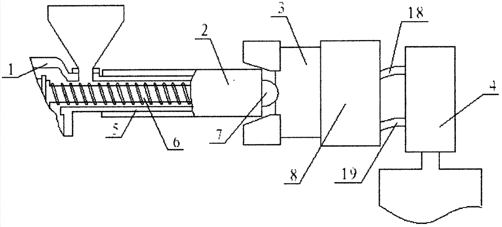
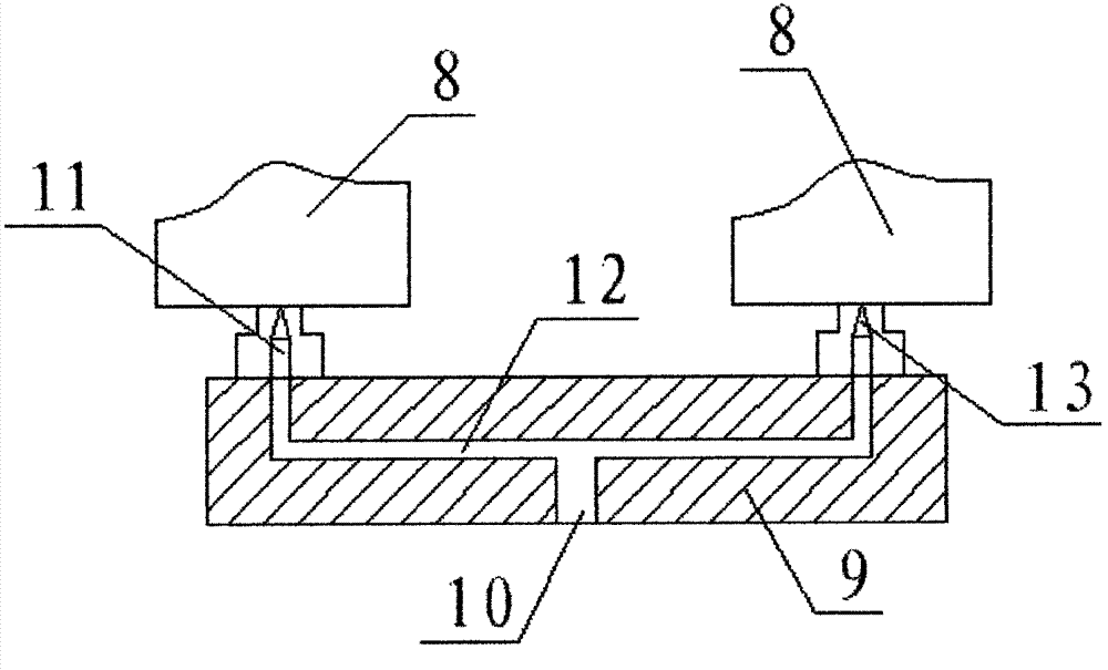
[0015] see figure 1 , figure 2 and image 3 As shown, the injection molding machine of a kind of material distribution injection molding of the present invention comprises feeding mechanism 1, and the injection device 2 that is connected with feeding mechanism 1, and the material distribution mechanism 3 that is connected with injection device 2, and with material distribution mechanism 3 an injection mold 8 that is matched and connected, and a water circulation mechanism 4 connected to the injection mold 8 through two water pipes, the injection device 2 includes a barrel 5, a screw 6, and a nozzle 7, and the screw 6 is arranged in the barrel 5, The nozzle 7 is arranged at the end of the barrel 5, and the material distribution mechanism 3 includes a material distribution body 9, and the material distribution body 9 is provided with a material inlet 10 correspondingly connected to the nozzle 7, opposite to the material inlet 10 More than one discharge port 11 is arranged on ...


PUM


Abstract

The invention discloses an injection molding machine for material separation injection molding, which comprises a charging mechanism, an injection device connected with the charging mechanism in a matching manner, a material separation mechanism connected with the injection device in a matching manner, an injection mold connected with the material separation mechanism in a matching manner, and a water circulation mechanism connected with the injection mold through two water pipes. The injection device comprises a charging barrel, a screw rod and a nozzle, wherein the screw rod is arranged in the charging barrel; and the nozzle is arranged at the tail end of the charging barrel. The material separation mechanism comprises a material separation body, wherein a material inlet connected with the nozzle in a corresponding manner is formed in the material separation body; more than one material outlet is formed on the end face opposite to the material inlet; the material inlet is communicated with a bifurcate delivery pipe in the material separation body; and the tail ends of the bifurcated delivery pipe are connected with the material outlets on the other end face of the material separation body respectively. With the adoption of the structure, after the injection mold is mounted, the uniformity of the mold temperature is ensured through the water circulation mechanism; a qualification rate of a product is increased; and the waiting time of the injection molding can be shortened effectively by utilizing the material separation mechanism.

Description

technical field [0001] The invention relates to an injection molding machine, in particular to an injection molding machine for split injection molding. Background technique [0002] Since one working cycle of the injection molding machine includes several processes, and the existing injection molding machine only performs one injection in one working cycle, the working efficiency of the injection molding mechanism is low. Especially electric injection molding machines are generally driven by expensive servo motors, and the servo motors spend most of their time waiting for other processes to be completed, resulting in low work efficiency. Contents of the invention [0003] The technical problem to be solved by the present invention is to provide an injection molding machine with high production efficiency and high product pass rate. [0004] The present invention is achieved through the following technical solutions: [0005] An injection molding machine for material dis...

Claims


Application Information

Patent Timeline
Patent Type & Authority Applications(China)
IPC IPC(8): B29C45/03B29C45/47B29C45/73B29C45/78B29C45/20
Inventor 张义清余一波
Owner 宁波赫仕机械制造有限公司
Why Eureka
Eureka Blog
Learn More