Check patentability & draft patents in minutes with Patsnap Eureka AI!

operation panel

An operation panel and panel technology, which is applied to the arrangement of accessories on the instrument panel, heating/cooling equipment, vehicle parts, etc., can solve the problems of light leakage, abnormal sound, and difficulty in assembling display panels, and achieves low prices, prevents floating, good looking effect

Inactive Publication Date: 2016-04-13
U SHIN LTD +1
View PDF5 Cites 0 Cited by
  • Summary
  • Abstract
  • Description
  • Claims
  • Application Information

AI Technical Summary

Problems solved by technology

[0007] However, when the circular display panel is bonded to the front surface of the panel body as in the past, the edge portion (cut line) of the display panel will be exposed, so there is a problem that the appearance of the operation panel will be deteriorated.
[0008] In order to solve the above-mentioned problems, one method is to apply deep drawing to the display panel, and bend the peripheral edge portion of the display panel toward the back side to form a bent portion, thereby hiding the cutting line. When fixing the bending part of the display board on the panel body by the bonding method, it is difficult to assemble the display board because the assembly direction is parallel to the bonding surface, and only the ring-shaped display part of the display board is fixed on the panel body
In addition, if the bent portion of the display panel is not fixed to the panel body, its end will float up, and a gap will be created between the bent portion of the display panel and the panel body, causing problems such as abnormal sound or light leakage.
[0009] As for other methods of fixing the display panel that has been drawn in the peripheral edge to the panel body, there is a method to integrate the display panel with the panel body by insert forming, but this method will cause the insert The metal mold for forming is complicated, resulting in high mold cost

Method used


Image

  • operation panel
  • operation panel
  • operation panel

Examples


Embodiment Construction

[0068] Embodiments of the present invention will be described below based on the drawings.

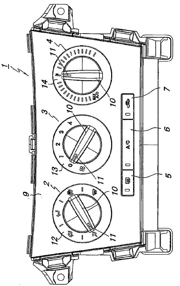
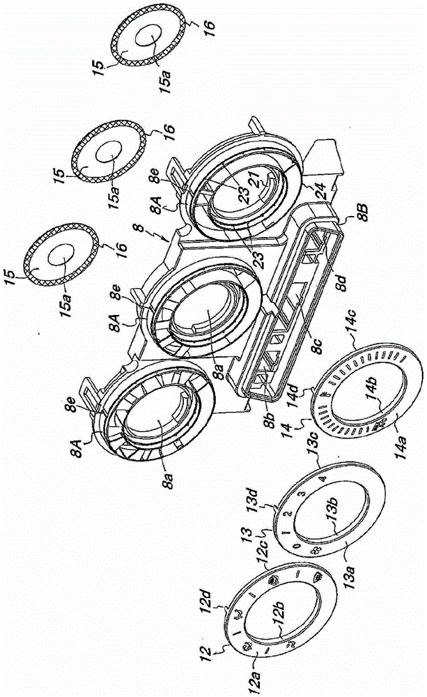
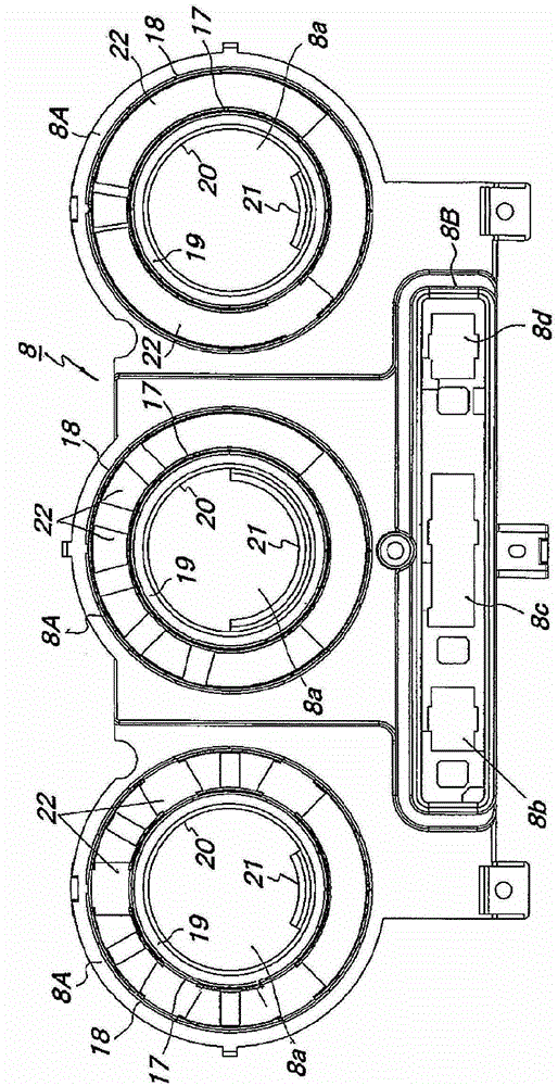
[0069] figure 1 is a front view of the operation panel of the present invention, figure 2 is an exploded perspective view of the same operation panel, image 3 It is the front view of the panel body of the same operation panel, figure 1 The operation panel 1 shown in is a device for controlling an unillustrated vehicle-mounted air conditioner. On its front surface, an air supply mode switch 2, an air volume adjustment switch 3, and a temperature adjustment switch 4 are arranged horizontally in sequence from left to right. . In addition, in the center portion in the width direction of the lower front surface of the operation panel 1, rear differential switches (Japanese: riadfusutsuchi) 5, air conditioner switches 6, and inside and outside air switching switches 7 are arranged horizontally from left to right. These rear differential switch 5, air conditioner switch 6 and inside and...


PUM


Abstract

The invention provides an operation panel. The panel body (8) of the operation panel has an opening (8a). The opening (8a) is used to install a rotatable operation knob that can be stopped at multiple selection positions. The opening (8a) is An annular display panel (12-14) for displaying the selected position is arranged around it, characterized in that the inner peripheral edge of the annular display portion (12a-14a) of the display panel (12-14) is and the outer peripheral edge is bent toward the back side to form bending portions (12b-14b), (12c-14c) respectively, and the bending of the display panel (12-14) is formed on the panel body (8). The cylindrical holding part (8A) holds the parts (12b to 14b) and (12c to 14c), and the inner and outer side walls of the holding part (8A) are separated by predetermined intervals along the circumferential direction. A plurality of first welding ribs (23) are formed at intervals, and the first welding ribs (23) are connected to the bent portions (12b-14b) and (12c-14c) of the display panels (12-14) by ultrasonic welding. ) join.

Description

technical field [0001] The invention relates to an operation panel equipped with a rotatable operation knob which can be stopped at a plurality of selection positions. Background technique [0002] For example, a vehicle is provided with an operation panel on which a rotary operation knob is mounted as a switching device for adjusting temperature and air volume of an air conditioner. Such an operation panel has an opening formed in the panel body for mounting an operation knob, and an annular display panel is arranged around the opening for displaying a selected position of the operation knob. [0003] Conventionally, on such an operation panel, an annular display panel is bonded to the front surface of the panel body (for example, refer to Patent Document 1). [0004] prior art literature [0005] patent documents [0006] Patent Document 1: Japanese Patent No. 3779472 [0007] However, when the circular display panel is bonded to the front surface of the panel body as ...

Claims


Application Information

Patent Timeline
Patent Type & Authority Patents(China)
IPC IPC(8): B60H1/00B60K37/06B60K35/10
Inventor 武田勝弘犬塚隆光
Owner U SHIN LTD
Features
  • R&D
  • Intellectual Property
  • Life Sciences
  • Materials
  • Tech Scout
  • Unparalleled Data Quality
  • Higher Quality Content
  • 60% Fewer Hallucinations
Learn More