Belt collecting and winding machine structure

A technology of coiling machine and barrel, which is applied in the structural field of coiling machine for strip material rewinding, can solve the problems affecting the tightness of the strip material, the deposition of the strip material, and the effect of the coil material, and achieve a good tensioning effect of the strip material Effect

Inactive Publication Date: 2013-04-17
NINGBO NINGCHUANG AUTOMATION DEVICE
View PDF3 Cites 7 Cited by
  • Summary
  • Abstract
  • Description
  • Claims
  • Application Information

AI Technical Summary

Problems solved by technology

The structure of the belt material rewinding and rewinding machine with this structure will have the following defects: (1). After the system is powered off, the rewinding cylinder will stop rotating immediately. At this time, the feeding mechanism will continue to feed due to inertia, which will cause A part of the strip material will deposit during the conveying process, and it will also affect the tightness of the strip material wound on the receiving drum, and affect the final coil effect; (2) There will be tension in the process of the strip material passing through these roller groups The degree of inconsistency, so that the tape material wound on the rewinding drum will have inconsistent tightness, which will also affect the final coil effect

Method used


Image

  • Belt collecting and winding machine structure
  • Belt collecting and winding machine structure
  • Belt collecting and winding machine structure

Examples


Embodiment Construction

[0023] The present invention will be described in further detail below in conjunction with the embodiments of the drawings.

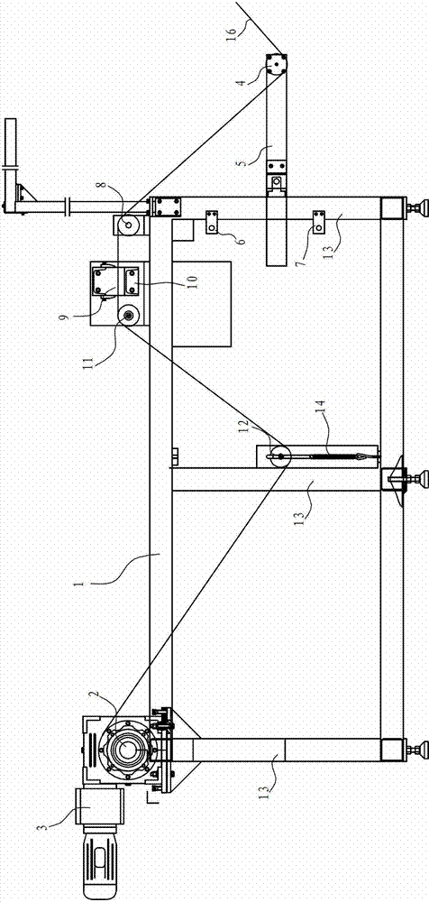
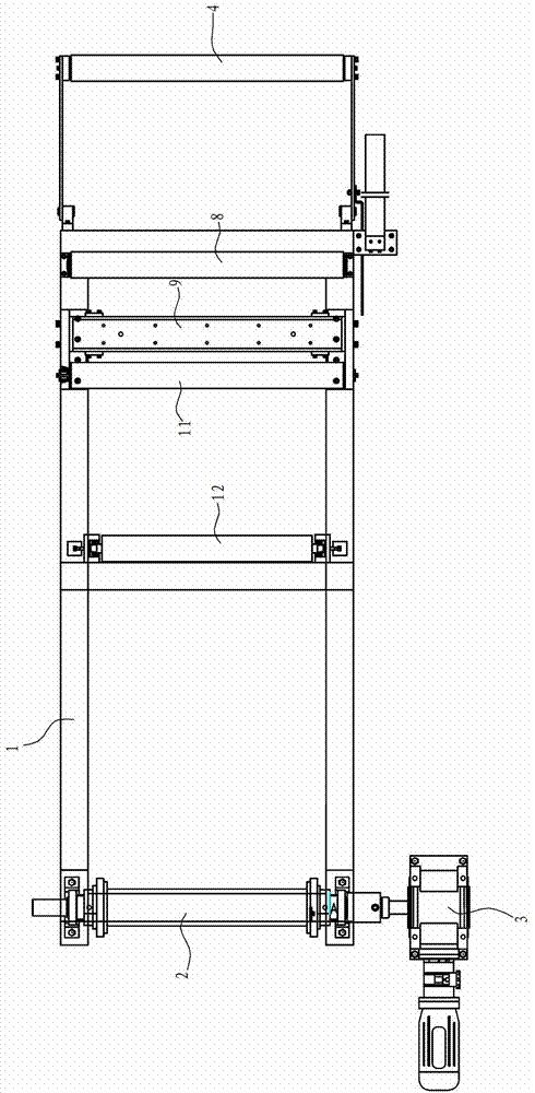
[0024] Such as figure 1 with 2 The structure of the tape rewinding and reeling machine shown includes:

[0025] Support frame, the support frame includes a support table 1 and a support foot 13;

[0026] The receiving barrel 2 set on the support table 1,

[0027] The receiving drive mechanism 3 that controls the rotation of the receiving barrel,

[0028] The first roller 4, the first roller is fixed at the first end of the pendulum rod 5, the middle part of the pendulum rod 5 is rotatably arranged on the supporting foot 13, and the conveyed belt material 16 first bypasses the first roller 4, The axis position of a roller 4 is lower than the axis position of the receiving drum 2;

[0029] The first limit switch 6 is arranged on the support foot 13 and is located above the pendulum rod 5, which can contact the second end of the pendulum rod 5 after rotating;

[0030...


PUM


Abstract

The invention relates to a belt collecting and winding machine structure. The belt collecting and winding machine structure comprises a support, a collecting barrel and a collecting driving mechanism, wherein the collecting barrel is arranged on the support, and the collecting driving mechanism controls the collecting barrel to rotate. The belt collecting and winding machine structure is characterized by further comprising a first roller, a first limit switch, a second limit switch, a second roller, an upper press plate, a lower press plate, a third roller and a fourth roller, wherein the first roller is fixed at a first end of a swing rod, the middle of the swing rod is rotationally arranged on the support, conveyed belts firstly wind on the first roller, the upper press plate and the lower press plate are fixed on the support, the lower press plate is arranged below the upper press plate and tightly arranged with the upper press plate, the third roller and the fourth roller are fixed on the support, the axis of the fourth roller is lower than the axis of the collecting barrel, and output ends of both the first limit switch and the second limit switch are connected with the collecting driving mechanism. Compared with the prior art, the belt collecting and winding machine structure can always guarantee constant tightness degree of belt winding.

Description

Technical field [0001] The invention relates to a tape-rewinding and reeling machine structure, which can be used for the reeling of metal or other materials. Background technique [0002] The existing tape-rewinding reel structure generally includes one or several roller sets with staggered axis positions, and the tape passes through these roller sets and then is collected in the reel. The structure of the tape-rewinding and reeling machine with this structure will have the following defects: (1) When the system turns off the power, the reeling cylinder immediately stops rotating. At this time, the feeding mechanism will continue to feed due to inertia, which will cause Part of the strip material is deposited during the conveying process, and it will also affect the tightness of the strip material wound on the receiving drum and affect the final coil effect; (2) There will be tension when the strip material passes through these roller groups. The degree of inconsistency, so tha...

Claims


Application Information

Patent Timeline
Patent Type & Authority Applications(China)
IPC IPC(8): B65H23/26
Inventor 张舜德谢建平
Owner NINGBO NINGCHUANG AUTOMATION DEVICE
Why Eureka
Try Eureka