Radial flow two-stage disc type magneto-rheological valve

A magneto-rheological valve and disk-type technology, which is applied in the direction of fluid pressure actuators, servo motor components, mechanical equipment, etc., can solve the problems of increasing the magnetic induction intensity of the damping gap, the difficulty of the length of the effective damping gap, and the blockage of the damping gap. Wide adjustable range of differential pressure, compact internal space and stable performance

Inactive Publication Date: 2015-02-04
EAST CHINA JIAOTONG UNIVERSITY
View PDF12 Cites 2 Cited by
  • Summary
  • Abstract
  • Description
  • Claims
  • Application Information

AI Technical Summary

Problems solved by technology

The commonly used method is to reduce the width of the damping gap of the magnetorheological valve, but when the magnetorheological fluid is left unused for a long time and restarted, particles are prone to precipitate and block the damping gap, resulting in the failure of the magnetorheological valve
Currently commonly used axial flow magneto-rheological valves are prone to such clogging due to too small damping gap design.
The second is to increase the length of the damping gap, which is difficult to achieve due to the limitations of the installation space and the structural size of the valve itself.
[0005] Based on this, in the actual design process, it is difficult to simultaneously increase the magnetic induction intensity in the damping gap and increase the length of the effective damping gap

Method used


Image

  • Radial flow two-stage disc type magneto-rheological valve
  • Radial flow two-stage disc type magneto-rheological valve
  • Radial flow two-stage disc type magneto-rheological valve

Examples


Embodiment Construction

[0018] Below in conjunction with accompanying drawing and embodiment the present invention will be further described:

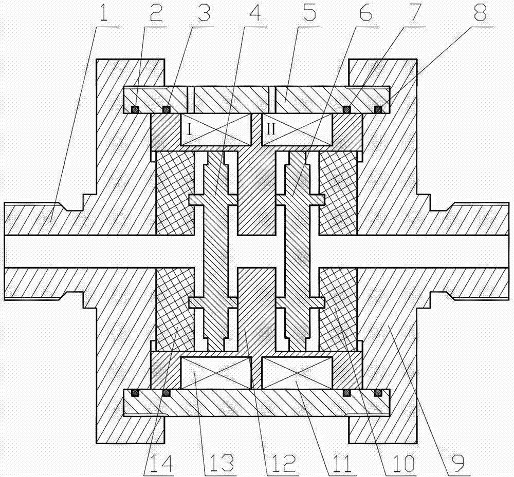
[0019] like figure 1 As shown, the present invention includes: left end cover 1, sealing ring I2, sealing ring II3, left damping disc 4, valve body 5, right damping disc 6, sealing ring III7, sealing ring IV8, right end cover 9, right positioning plate 10. Coil II11, spool 12, coil I13 and left positioning disc 14. The left end cover 1 and the valve body 5 are fixedly connected by threads, and a sealing ring I2 is arranged between the left end cover 1 and the valve body 5 . The spool 12 is in clearance fit with the valve body 5, and a sealing ring II3 and a sealing ring III7 are arranged between the spool 12 and the valve body 5. The coil I13 is wound in the winding groove I of the valve core 12 , and the coil II11 is wound in the winding groove II of the valve core 12 . When assembling, first insert the lead wires of coil I13 and coil II11 into the two co...


PUM


Abstract

The invention discloses a radial flow two-stage disc type magneto-rheological valve which is composed of an end cover, a valve element, a valve body, a positioning disc, a damping round disc, coils and a sealing ring. When certain intensity current in a certain direction is respectively input into the coil I and the coil II, magnetorheological fluids in damping gaps produce magnetic induction intensity under the action of magnetic fields. By means of adjustment of intensities of the current in the two coils, pressure difference control in the four damping gaps can be achieved. According to the magneto-rheological valve, radial flow two-stage disc type damping gap structures fully utilize walking directions of magnetic lines of forces, the length of the damping gaps of the valve is effectively increased, and simultaneously, the magnetic induction intensity in the damping gaps is improved; the enough pressure difference of the magneto-rheological valve is guaranteed, blocking of the valve is absent, performances of the valve are stable, and adjustable ranges of the pressure difference are wide; and the damping gaps of the magneto-rheological valve are accurate in positioning, interior structures are compact, the size is small, the assembling is convenient, and the magneto-rheological valve is particularly applicable to multistage pressure-adjustable low-pressure small flow hydraulic control systems.

Description

technical field [0001] The invention relates to a magnetorheological valve, in particular to a radial flow two-stage disc magnetorheological valve. Background technique [0002] In the hydraulic control system, the hydraulic control valve is mainly used to control the pressure, flow and flow direction of the liquid flow in the hydraulic actuator, so as to control the start and stop of the hydraulic actuator, change the speed, direction, force and action sequence of the movement, etc. Meet the requirements of various hydraulic equipment for load conditions such as motion, speed, force and torque. Therefore, the performance of the hydraulic control valve directly affects the static characteristics, dynamic characteristics and working reliability of the hydraulic system, and is one of the core control units in the hydraulic control system. With the development of high technology, the engineering application of hydraulic transmission has higher and higher requirements for hydra...

Claims


Application Information

Patent Timeline
Patent Type & Authority Patents(China)
IPC IPC(8): F15B13/02
Inventor 胡国良龙铭黄敏李海燕喻理梵
Owner EAST CHINA JIAOTONG UNIVERSITY
Why Eureka
Try Eureka