A gear unit and a method for controlling a lubrication pump of a gear unit

A gear unit and lubricating pump technology, applied in gear lubrication/cooling, engine lubrication, transmission control, etc., can solve the problem of long duration of cold start process

Active Publication Date: 2013-04-17
MOVENTAS GEARS
View PDF4 Cites 6 Cited by
  • Summary
  • Abstract
  • Description
  • Claims
  • Application Information

AI Technical Summary

Problems solved by technology

However, this sometimes leads to situations where the du

Method used


Image

  • A gear unit and a method for controlling a lubrication pump of a gear unit
  • A gear unit and a method for controlling a lubrication pump of a gear unit

Examples


Embodiment Construction

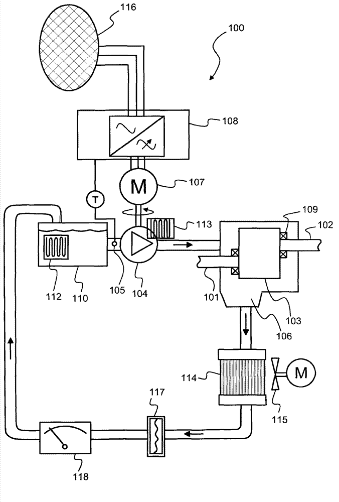
[0032] figure 1 A schematic diagram of a gear unit 100 according to an advantageous exemplary embodiment of the invention is shown. The gear unit comprises a first shaft 101 and a second shaft 102 for connection to an external mechanical system. The external mechanical system may for example but not necessarily comprise a wind turbine connectable to the shaft 101 and a generator connectable to the shaft 102 ie the gear unit can eg be a gear unit suitable for wind energy applications. The gear unit comprises at least one gear stage 103 between shafts 101 and 102 . The at least one gear stage may eg comprise one or more planetary gear stages, one or more spur gear stages and / or one or more bevel gear stages, or a combination of the aforementioned kinds of gear stages. The gear unit comprises a lubricating pump 104 for circulating lubricating oil through at least one gear stage of the gear unit and bearings 109 . The lubricating pump can be, for example, a gear pump. exist f...


PUM


Abstract

A gear unit comprises shafts (101,102) for connecting to an external mechanical system, at least one gear stage (103) between the shafts, a lubrication pump (104) for circulating lubricating oil through the at least one gear stage and bearings of the gear unit, a temperature sensor (105) for measuring temperature of the lubricating oil and supplying a temperature signal, an electrical motor (107) for driving the lubrication pump, and an electrical device (108) for controlling the electrical motor so that torque directed to the lubrication pump is below a torque limit. The torque limit is determined dynamically on the basis of the measured temperature of the lubricating oil.

Description

technical field [0001] The invention relates to a gear unit and to a method for controlling a lubrication pump of a gear unit. Furthermore, the invention relates to a computer program for controlling a lubrication pump of a gear unit. Background technique [0002] A lubrication system of a gear unit typically comprises a lubrication pump arranged to circulate lubricating oil through the gear stage or stages of the gear unit and through the bearings of the gear unit. Since the viscosity of lubricating oil is mainly dependent on temperature, the lubricating pump must be designed and operated in such a way that the lubricating pump cannot be damaged even when the lubricating oil is cold and therefore its viscosity is relatively high. [0003] In principle, it is possible to preheat the lubricating oil so that the lubricating oil is in all cases warm enough to be pumped in the same way as during normal use of the gear unit. However, the warm-up to make the lubricating oil warm...

Claims


Application Information

Patent Timeline
IPC IPC(8): F16H57/04
CPCF16H57/0413F16H57/0434F16N2250/08F16N7/385F16H57/022F16H57/04F16H61/0031F16H2312/14F16H59/72F04B2203/021F04B2203/0207F04B2203/0209
Inventor 卡里·乌西塔洛尤卡·埃尔弗施特罗姆
Owner MOVENTAS GEARS
Why Eureka
Try Eureka