Multi-magnetic block position-adjustable turntable sensor for assisted bicycle

An adjustable technology for power-assisted bicycles, which is applied in the direction of transmission of sensing components, vehicle components, riders, etc., using electric/magnetic devices, and can solve the problem of no control signal, incompatibility, and permanent magnets that cannot indicate pedal rotation Location etc.

Inactive Publication Date: 2012-11-21
QINZHOU IND RES INST
View PDF7 Cites 3 Cited by
  • Summary
  • Abstract
  • Description
  • Claims
  • Application Information

AI Technical Summary

Problems solved by technology

[0015] Disadvantages (1) Using two permanent magnetic steels with no difference to represent the fixed positions of the two pedals, only multiple Halls can be used to represent the rotational positions of the pedals: the two magnetic steels have no difference, and the advantages are The fixed position of the two pedals can be indicated regardless of the left and right feet, so that the left and right feet can generate power assistance requirements, which can produce the same motor power assistance effect; but the disadvantage is that the permanent magnet itself cannot indicate the rotational position of the pedals, but can only Use multiple Halls at different corner positions to indicate the rotational position of the pedal, so you cannot use only one Hall, but must use multiple Halls
[0016] Disadvantage (2) Only one Hall cannot be used, but three Halls will inevitably cause the original segmentation error of the three control signals, which will distort the power-assist demand model, naturally The generation of power output is inconsistent with the demand for power assistance: no matter whether the power-assisted bicycle has one or two motors, the sensor signal for controlling the motor can only be controlled by using one sensor signal input to the motor controller; and the patent uses three sensors. If Hall controls the motor, the three control signals of the three Halls must be combined into one combined control signal before it can be input to the motor controller
The sensing parameters of the three Halls cannot be the same, especially due to changes in ambient temperature and long-term use, the sensing parameters of the three Halls may vary greatly. The output voltages are different, resulting in different power output of the motor, and the power output is inconsistent with the power demand; similarly, when the power demand is the same, the outputs of different Halls may be the same voltage, resulting in the same power output of the motor, and also There is a problem that the power output is inconsistent with the power demand
[0017] Disadvantages (3) The combined control signal is prone to signal drift, which makes the combined control signal not match the motor controller, and the power-assisted demand model is distorted: due to changes in ambient temperature and use time After a long period of time, the sensing parameters of the three Halls may vary greatly, and the connection points of the three control signals of the three Halls will inevitably change, so the combined control signals generated by the same boosting demand will produce segmental signal drift. Combining the control signals as a whole produces signal distortion, that is, the power-assist demand model is distorted, causing the motor controller to choose any one of the three control signals as a reference, resulting in the inconsistency between the power-assisted output and the power-assisted demand
[0018] Disadvantages Sensing points cannot be increased arbitrarily, if there are too few sensing points, the operation of the motor will not be stable, making the rider feel very uncomfortable: due to the disadvantages (1) and disadvantage (2) are most caused by the number of Halls being greater than one. Obviously, the more the number of Halls, the more serious the disadvantages (1) and (2) are.
Therefore, the power-assisted bicycle provided by this patent can only be a very bad power-assisted bicycle that makes the rider feel comfortable.
[0019] Disadvantages (5) The signal blind area reaches 42 degrees, and when the power is needed when starting, it is impossible to get it: as we all know, the torque of the bicycle pedal is the smallest at the apex , from the angle of 10-45 degrees away from the top is the area that needs the most assistance, but the angle between the Halls in this patent is 42.5-43.5 degrees, and there is no Hall in the area of ​​10-42 degrees away from the top of the pedal. There is no control signal, and the result is when the assist is most needed, but the motor of the assist bicycle cannot assist
[0020]In a word, this patent is a technical solution of using multiple Halls to control the booster mode, because only multiple Halls can be used to represent the rotation position of the pedal, and multiple Halls The multiple control signals of Hall must have original errors, and the combined control signals are prone to signal drift, which can cause distortion of the assist demand model, that is, the same assist demand at different times, but different assist effects; the more the number of Halls, the more More, the more serious the distortion of the power-assisted demand model is, the quantity is limited, and the less quantity of Hall causes the motor to run unsteadily, which makes the rider feel very uncomfortable and cannot get power-assisted when starting
To make it undistorted to help the demand model, and to ensure the smooth operation of the motor, there are always two issues. It is impossible to have both.

Method used


Image

  • Multi-magnetic block position-adjustable turntable sensor for assisted bicycle
  • Multi-magnetic block position-adjustable turntable sensor for assisted bicycle
  • Multi-magnetic block position-adjustable turntable sensor for assisted bicycle

Examples


Embodiment 1

[0113] Embodiment 1. A turntable sensor with adjustable multi-magnet positions for power-assisted bicycles

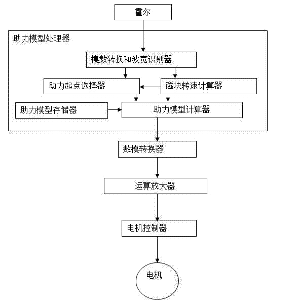
[0114] Such as figure 1 , 3 , the sensor in this embodiment includes a sensor element connected in sequence, a booster model processor 21, a digital-to-analog converter 27 and an operational amplifier 28;

[0115] [1] The sensing element is an element that converts the rotational motion of the rotating disk 1 into a rectangular wave signal output;

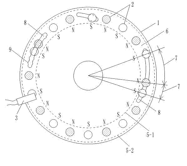
[0116] The sensing element is to use a high-strength plastic rotating disk 1 with a diameter of 10.0 cm to set 20 permanent magnets 2 with a diameter of 0.8 cm on one surface, and the magnetic flux is 146---279 (B·H)max / KJ·m -3 a value in . The structure of rotating disk 1, permanent magnet block 2 and Hall 3 is as follows:

[0117] Each permanent magnet block 2 is fixed in the circular ring 6 range between the circular trajectory line 5-1-9.5 cm outer circular trajectory line 5-2 with a diameter of 8.0 cm, and there ...

Embodiment 2

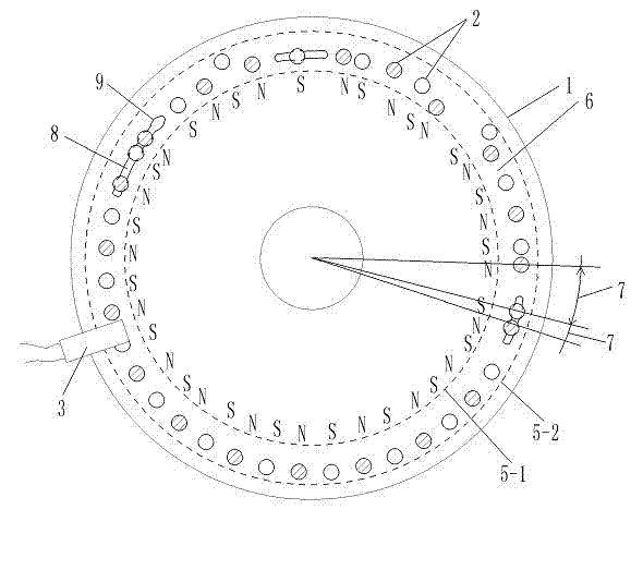
[0134] Embodiment 2. A multi-magnet position-adjustable turntable sensor for high-density power-assisted bicycles

[0135] Such as figure 2 , 3 1. A high-strength aluminum rotating disk 1 with a diameter of 10.0 cm is provided with 40 permanent magnet blocks 2 with a diameter of 0.6 cm. The magnetic flux of the permanent magnet block 2 is 146---279 (B·H)max / KJ·m -3 A certain value, Hall 3 keeps a distance of 0.2 cm from each permanent magnet block 2 in the rotating state, so that when each rotating permanent magnet block 2 passes through Hall 3, Hall 3 can generate a corresponding Rectangular wave signal output. Other structures are the same as in Embodiment 1.

Embodiment 3

[0136] Embodiment 3, a turntable sensor with adjustable multi-magnet positions for power-assisted bicycles with specific circuits

[0137] Such as figure 1 , 4 , the sensor in this embodiment includes a sensor element connected in sequence, a booster model processor 21, a digital-to-analog converter 27 and an operational amplifier 28;

[0138] [1] The Hall 3 in the sensing element is UGN3075; the structure of other elements and elements in the sensing element is the same as that in Embodiment 1;

[0139] [2] The auxiliary model processor 21 selects the single-chip microcomputer 31 to complete all functions, and the single-chip microcomputer 31 selects AT89S52. That is, the AT89S52 single-chip microcomputer 31 completes all functions of the analog-to-digital conversion and the wave width identifier 22 , the power-assisted starting point selector 23 , the magnet speed calculator 24 , the power-assisted model memory 25 and the power-assisted model calculator 26 .

[0140] [3]...


PUM


Abstract

The invention discloses a multi-magnetic block position-adjustable turntable sensor for an assisted bicycle, and belongs to the technology of providing a control signal by performing multi-point magnetic induction. The multi-magnetic block position-adjustable turntable sensor for the assisted bicycle comprises a sensing element, an assistance model processor, a digital-to-analogue converter and an operational amplifier which are connected in sequence; the sensing element is a plurality of permanent magnet blocks with adjustable space which are arranged on a turntable; the magnetic polarities of adjacent permanent magnet blocks are opposite, namely the distribution way is pole N, pole S, pole N, ellipsis; and a Hall element is arranged at the position close to the permanent magnet blocks. The multi-magnetic block position-adjustable turntable sensor for the assisted bicycle has the advantages that the Hall element can acquire square-wave signals by utilizing the NS opposite distribution way of the magnetic polarities of the adjacent permanent magnet blocks, and digital processing of the signals is facilitated; the square-wave signals can represent the positions of the permanent magnet blocks on the turntable by adjusting the distance among the permanent magnet blocks, and the application of different square waves are determined; and the sensor can output control model electric signals which are matched with the movement position of the permanent magnet blocks and are set artificially.

Description

technical field [0001] The invention belongs to the technical field of providing signals by magnetic induction, and in particular relates to the technology of providing control signals by multi-point magnetic induction on a rotating component. Background technique [0002] The Chinese patent 201020295192.0 "Claw Type Torque Sensing Device" applied by Yebao Vehicle Material Industry (Kunshan) Co., Ltd. discloses a sensing device for power-assisted bicycles. The sensing device includes a magnetic part and an elastic part to sense the torque. sensing device. After a long time of use, the change of the elastic coefficient of the elastic member will lead to changes in the sensing signal and the control effect of the controlled motor, and the power-assisted effect will not match the power-assisted needs of people. Moreover, the design structure of the elastic member is complex and the manufacturing cost is high. [0003] The Chinese patent 01201843.0 "Automatic Detection Device ...

Claims


Application Information

Patent Timeline
Patent Type & Authority Applications(China)
IPC IPC(8): B62M6/50G01D5/244
Inventor 黄强
Owner QINZHOU IND RES INST
Why Eureka
Try Eureka