
Water hammer discharge valve

A discharge valve and water hammer technology, applied to valve details, safety valves, balance valves, etc., can solve the problems of secondary instantaneous high pressure, excessive closing speed of discharge valve, etc., to eliminate water hammer and avoid secondary water Hammer, quick opening effect

Active Publication Date: 2013-04-17
WUHAN DAYU VALVE
View PDF4 Cites 8 Cited by
  • Summary
  • Abstract
  • Description
  • Claims
  • Application Information

AI Technical Summary

Problems solved by technology

[0004] The purpose of the present invention is to solve the shortcomings of the above-mentioned background technology, and provide a water hammer relief valve, which can not only be opened quickly to eliminate water hammer, but also can solve the secondary instantaneous high pressure caused by the excessive closing speed of the relief valve itself The problem

Method used


Image

  • Water hammer discharge valve

Examples


Embodiment Construction

[0019] The present invention will be further described in detail below in conjunction with the accompanying drawings and specific embodiments to facilitate a clear understanding of the present invention, but they do not limit the present invention.

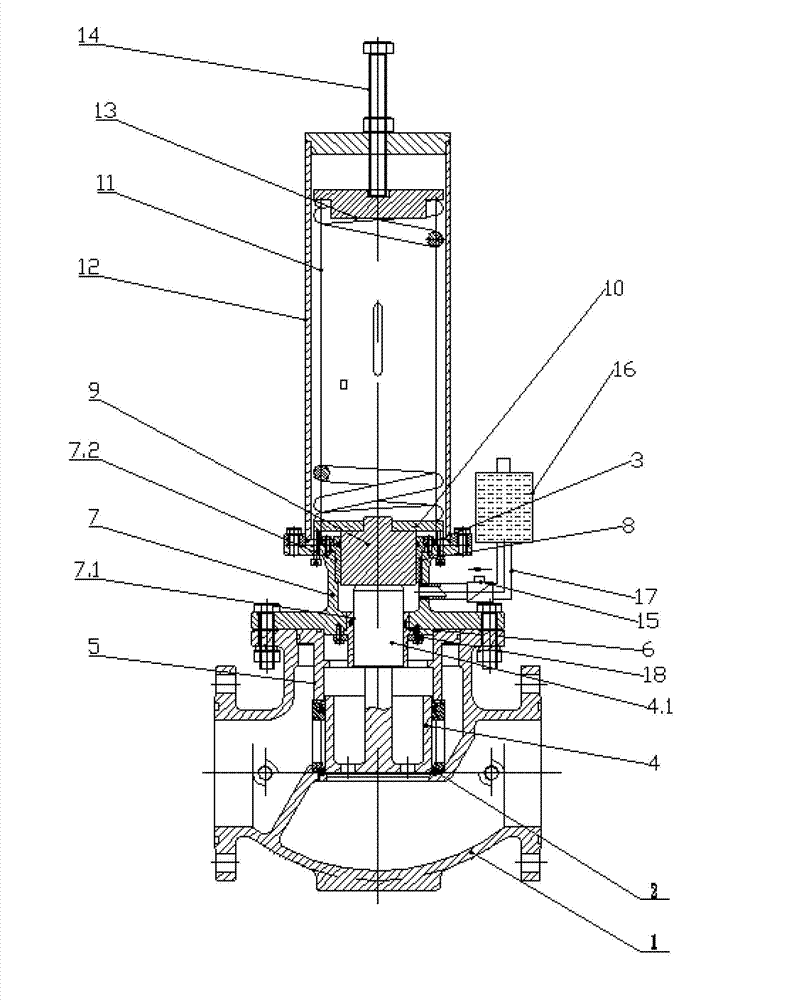
[0020] like figure 1 The water hammer relief valve shown includes a valve body 1 and a casing 12 integrally connected by a connecting seat 7, and the connecting seat 7 is fixedly connected to the valve body 1 and the casing 12 by bolts respectively. The valve seat 2 and the valve disc 4 cooperate with each other in the valve body 1, and the valve disc 4 is provided with a central axis 4.1.

[0021] A pressure regulating system is provided in the casing 12, and the pressure regulating system includes an adjusting screw 14 and a spring 11. The adjusting screw 14 passes through the upper end surface of the casing 12, the spring 11 is arranged inside the casing 12, and the adjusting screw 14 and the spring Positioning plates 13 are a...


PUM


Abstract

The invention discloses a water hammer discharge valve. The water hammer discharge valve comprises a valve body and a casing pipe both connected through a connecting base, wherein the valve body is internally provided with a valve seat and a valve clack both of which are matched mutually; the valve clack is provided with a central shaft; the casing pipe is internally provided with a pressure adjusting system; a central hole matching with the central shaft of the valve clack is arranged at the lower end of the connecting base; an inner hole which is communicated with the central hole is arranged at the upper end of the connecting base; the central shaft of the valve clack penetrates through the central hole of the connecting base; a piston is arranged between the central shaft of the valve clack and the pressure adjusting system; the piston is arranged in the inner hole of the connecting base in a sealing manner; the side surface of the connecting base is also communicated with an oil cup through a connecting pipe; and the connecting pipe is provided with a one-way throttle valve. The water hammer discharge valve has a simple structure and a rational design, can be turned on rapidly to remove the water hammer, can be closed slowly to avoid second water hammer generated caused by the too rapidly closed valve, and has a very great practical value.

Description

technical field [0001] The invention relates to the technical field of valves, in particular to a quick-opening and slow-closing water hammer relief valve suitable for clean water pipeline systems. Background technique [0002] At present, pressure relief safety valves are generally used in clean water pipeline systems. These valves are direct-acting quick-opening and quick-closing or pilot-operated relief valves. After setting the value, open the pressure relief; but when the pump is stopped suddenly, this type of valve will be closed quickly, causing the circulation flow rate in the valve outlet pipeline to drop suddenly, and the return shock pressure will be generated. High, can make the pressure of the outlet section of the valve rise to several times of the rated pressure, which is the water hammer phenomenon in the pipeline, which can cause the valve or pipeline to rupture and cause an accident. [0003] Due to the rapid instantaneous high pressure generated by water ...

Claims


Application Information

Patent Timeline
Patent Type & Authority Applications(China)
IPC IPC(8): F16K17/10F16K17/06F16K47/02
Inventor 李习洪周超
Owner WUHAN DAYU VALVE
Learn More