
Optical device measuring method and measuring device

A measurement method and technology of optical devices, applied in the direction of testing optical performance, etc., can solve the problem of small measurement range and achieve the effect of expanding the measurement range

Active Publication Date: 2013-04-17
NANJING UNIV OF AERONAUTICS & ASTRONAUTICS
View PDF5 Cites 22 Cited by
  • Summary
  • Abstract
  • Description
  • Claims
  • Application Information

AI Technical Summary

Problems solved by technology

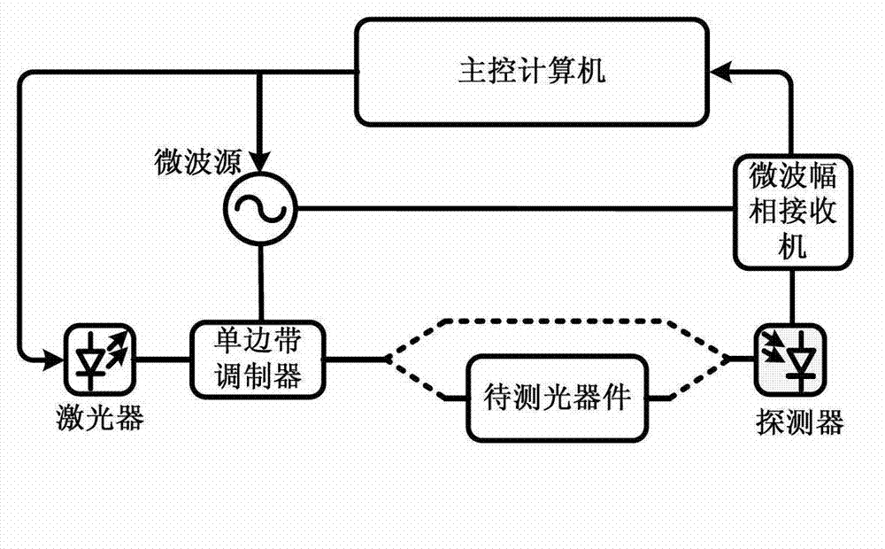
[0004] Although the measurement device has unparalleled measurement accuracy (in theory, it can reach the same accuracy as the electric spectrum analysis technology), but limited by the frequency sweep bandwidth of the microwave frequency sweep source (about 40GHz), it can only measure about 40GHz at the optical carrier frequency The transfer function of optical devices in the bandwidth range is difficult to adapt to the working range of several THz optical devices
The small measurement range is the biggest obstacle to the practicality of this technology, and there is no report of an effective solution

Method used


Image

  • Optical device measuring method and measuring device
  • Optical device measuring method and measuring device
  • Optical device measuring method and measuring device

Examples


Embodiment Construction

[0017] The technical scheme of the present invention is described in detail below in conjunction with accompanying drawing:

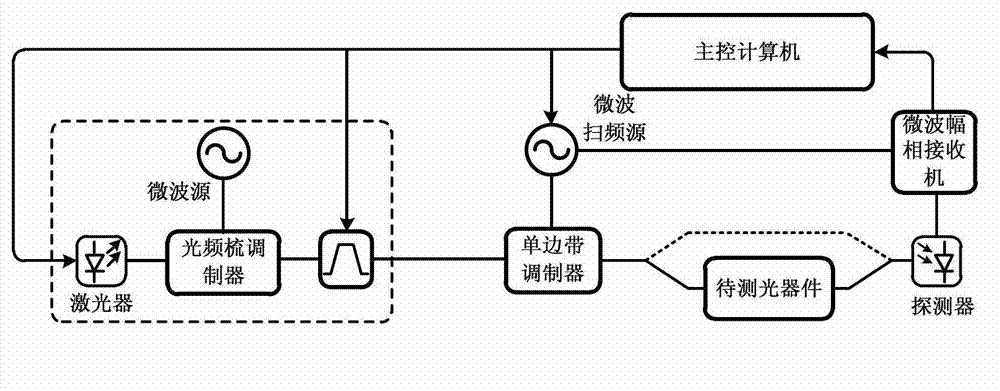
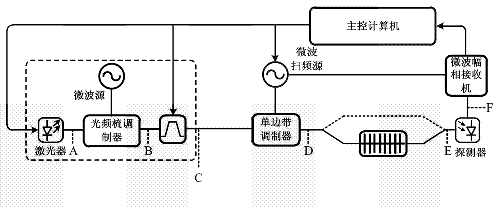
[0018] The idea of ​​the present invention is based on the existing optical device measurement method based on optical single-sideband modulation, and adopts the cooperative work mode of optical frequency comb and photon filter to sequentially generate multiple optical carriers of continuous frequency bands, and measure the optical The transfer function of the device in each frequency band can be obtained by numerical processing to obtain the transfer function of the broadband, thereby realizing the expansion of the measurement range. The measuring method of the present invention specifically comprises the following steps:

[0019] Step A, using an optical frequency comb modulator to modulate a microwave signal with a fixed frequency and phase onto the optical carrier output by the light source to generate an optical frequency comb; using a photon filte...


PUM


Abstract

The invention discloses an optical device measuring method which comprises the following steps that A, a microwave signal with fixed frequency and phase is modulated to a light carrier which is output by a light source through an optical frequency comb modulator, so as to generate an optical frequency comb; a plurality of continuous comb teeth of the optical frequency comb are filtered in sequence by a photonic filter; B, each filtered comb tooth serves as the light carrier, and the transmission functions of an optical device to be measured in a frequency band which corresponds to the comb tooth are measured through the optical device measuring method based on the unilateral modulation of light; and C, the broadband transmission functions of the optical device to be measured in the frequency bands which correspond to a plurality of continuous comb teeth are obtained according to the transmission functions in the frequency bands which correspond to all the comb teeth. The invention also discloses an optical device measuring device which adopts the method. According to the optical device measuring method and the measuring device, the optical frequency comb modulator works together with the photonic filter in a cooperate mode based on the optical device measuring method of the unilateral band modulation of light in the prior art, so that the measuring scope is greatly expanded.

Description

technical field [0001] The invention relates to an optical device measurement method and a measurement device, in particular to an optical device measurement method and a measurement device based on optical single sideband modulation, and belongs to the technical fields of optical device measurement and microwave photonics. Background technique [0002] With the rapid development and continuous improvement of photonic technology, photonic systems have higher and higher requirements for optical devices. To develop high-precision optical devices, high-precision measurement technology must be supplemented. However, the existing optical device measurement technology is not enough to achieve such a high test accuracy, so that breakthroughs in the development of high-precision optical devices cannot be achieved. At the same time, some existing high-precision optical devices cannot be used to maximize their effectiveness in photonic systems . In order to achieve ultra-high-precisi...

Claims


Application Information

Patent Timeline
Patent Type & Authority Applications(China)
IPC IPC(8): G01M11/02
Inventor 潘时龙薛敏唐震宙赵永久朱丹郭荣辉何超
Owner NANJING UNIV OF AERONAUTICS & ASTRONAUTICS
Learn More