Optical module structure

An optical module and structure technology, applied in the coupling of optical waveguides, etc., can solve problems such as high flatness, troublesome manufacturing, and low optical coupling efficiency of received light

Inactive Publication Date: 2013-04-17
ADVANCED SEMICON ENG INC
View PDF3 Cites 9 Cited by
  • Summary
  • Abstract
  • Description
  • Claims
  • Application Information

AI Technical Summary

Problems solved by technology

[0005] However, the outer inclined surface of the microreflector needs to be plated with gold (Au) or aluminum (Al) in addition to extremely high flatness (the general precision is required to be calibrated at 1/6 of the wavelength) in manufacture. Highly reflective metal, so it

Method used


Image

  • Optical module structure
  • Optical module structure
  • Optical module structure

Examples


Embodiment Construction

[0015] In order to make the above-mentioned purposes, features and advantages of the present invention more obvious and understandable, the preferred embodiments of the present invention will be specifically cited below, together with the accompanying drawings, for a detailed description as follows:

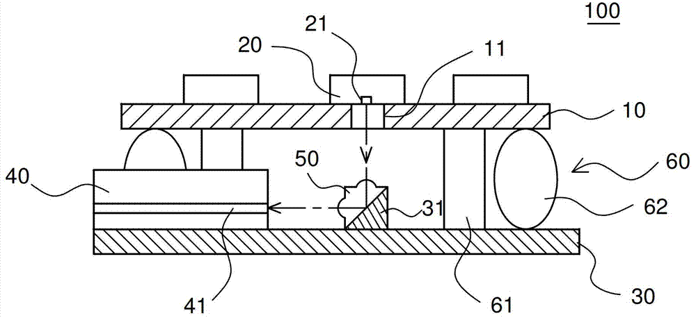
[0016] Please refer to figure 1 as shown, figure 1 It is a side sectional view of an optical module structure according to an embodiment of the present invention. An optical module structure 100, for example, is a packaging module structure made by micro-electromechanical (MEMS) technology, and the optical module structure 100 includes: a first substrate 10, a first optical element 20, a second substrate 30, a The second optical element 40 and a prism 50 . The first optical element 20 is disposed on the upper surface of the first substrate 10 , and the first optical element 20 has a first optical function portion 21 vertically downward. In this embodiment, the first optical el...


PUM


Abstract

The invention discloses an optical module structure. The optical module structure comprises a first optical element, a second optical element and a prism. The prism is a lens with a triangular or trapezoid cross section and is positioned below an optical action part of the first optical element. The prism is provided with a first side surface, a second side surface and a total internal reflection inclined plane, wherein a first spherical raised part is also formed on the first side surface, and a second spherical raised part is also formed on the second side surface. Lights which are sent from the first optical element are emitted into the prism through the first spherical raised part to form parallel lights, are turned for 90 degrees through the total internal reflection inclined plane, are emitted from the prism through the second spherical raised part to form focus convergent lights and are received by the second optical element. The prism can turn the lights of the optical elements, and the spherical raised parts of the prism can appropriately correct the divergence angels of the lights.

Description

technical field [0001] The invention relates to an optical module structure, in particular to an optical module structure for correcting the divergence angle of light and turning the light through a prism with a spherical convex portion on the surface. Background technique [0002] Early telecommunication transmissions (such as networks) were transmitted by radio signals. However, radio signals are prone to attenuation and interference during transmission, and there are also problems such as numerous contacts and easy disconnection. In recent years, due to the development of optical fiber technology and the advantages of anti-interference and attenuation of light wave signals, the transmission of light wave signals instead of electrical signals has become the driving force of signal transmission. [0003] Furthermore, in traditional semiconductors, electrical signals are mostly used to operate. However, due to the above-mentioned innate advantages of optical signals compared...

Claims


Application Information

Patent Timeline
IPC IPC(8): G02B6/42
Inventor 邱建良温安农余声宏何信颖简钰庭赖逸少
Owner ADVANCED SEMICON ENG INC
Why Eureka
Try Eureka