Athermal lens

A heat-absorbing difference and lens technology, applied in the optical field, can solve problems such as aiming error, high adjustment accuracy requirements, increase system size and weight, etc., and achieve the effects of cost reduction, simple assembly, and compact structure

Inactive Publication Date: 2013-04-17
NANJING WAVELENGTH OPTO ELECTRONICS SCI & TECH CO LTD
View PDF2 Cites 6 Cited by
  • Summary
  • Abstract
  • Description
  • Claims
  • Application Information

AI Technical Summary

Problems solved by technology

Although the electromechanical active and mechanical passive systems are easy to implement, they increase the size and weight of the system, and require high adjustment accuracy, which can easily cause optical axis shaking and cause aiming errors; the optical passive athermal system has small size, light weight, and simple structure. , stable optical axis, high reliability, etc.

Method used


Image

  • Athermal lens
  • Athermal lens

Examples


Embodiment Construction

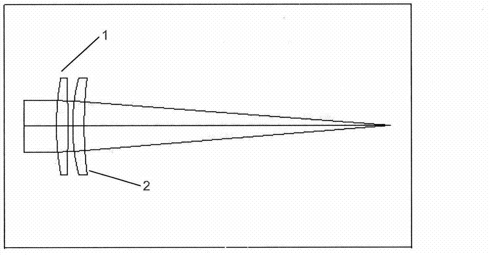
[0008] Such as figure 1 As shown, the present invention consists of lenses 1, 2 of different materials. The working principle of the invention is to use two lenses of different materials to eliminate thermal deformation of the laser.

[0009] The specific principle is: when the laser is irradiated on the lens, the thermal expansion of the lens increases the focal length, which affects the optical performance. At this time, lenses of two different materials are used, and the refractive index of the two materials will be affected by the temperature, which will cause the refractive index to decrease. Through scientific calculation, the focal length reduced by the refractive index change and the focal length increased by thermal deformation can be offset to keep the original focal length unchanged.

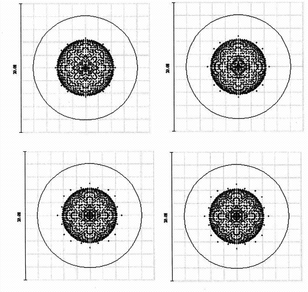
[0010] figure 2 It is a schematic diagram of the light spots of the present invention at different temperatures.


PUM


Abstract

The invention relates to an athermal lens, which adopts a two-piece spherical design. A piece of quartz glass with acid resistance and extremely small thermal expansion coefficient is adopted as a first piece of lens, both the first and the second surfaces of the first piece of lens are spherical surfaces, and a diaphragm is located on the first surface; fluorite is adopted as a second piece of lens, and both surfaces of the lens are spherical surfaces. The principle of the athermal lens is as follows: when being irradiated by laser, a lens is heated to expand, so that the focal length is increased, and as a result, the optical performance is affected; at the moment, the two lenses made of the different materials are used, the refractive index of the two materials can be affected by temperature to decrease; and by scientific calculation, the focal length decreased by the change of the refractive index can counteract the focal length increased by thermal deformation, so that the original focal length can be kept unchanged.

Description

technical field [0001] The invention relates to the field of optics, and is an athermal lens. Background technique [0002] Optical systems usually require stable optical performance within a certain temperature range, and most optical materials have a light-thermal expansion coefficient. As the ambient temperature changes, the refractive index of the optical material, the curvature and thickness of the optical element, and the spacing of the parts will all change. Changes will cause thermal defocusing of the optical system, resulting in poor imaging quality. Therefore, athermal optical systems have become an important research direction for high-precision systems. [0003] The athermal design of the optical system generally uses mechanical, optical, electronic and other technologies to keep the imaging quality of the system stable in a large temperature range. There are usually three methods: electromechanical active, mechanical passive, and optical passive. Although the e...

Claims


Application Information

Patent Timeline
Patent Type & Authority Applications(China)
IPC IPC(8): G02B13/00G02B1/00
Inventor 朱敏王国力吴玉堂黄胜弟谢玉春梁思远刘旭东
Owner NANJING WAVELENGTH OPTO ELECTRONICS SCI & TECH CO LTD
Why Eureka
Try Eureka