Method and apparatus for identifying and correcting spherical aberrations in a microscope imaging beam path

An imaging optical path and microscopic imaging technology, applied in the field of spherical aberration devices, can solve problems such as insufficient elimination of spherical aberration, and achieve the effect of eliminating spherical aberration

Inactive Publication Date: 2013-04-17
LEICA MICROSYSTEMS CMS GMBH
View PDF13 Cites 7 Cited by
  • Summary
  • Abstract
  • Description
  • Claims
  • Application Information

AI Technical Summary

Problems solved by technology

Known methods for compensating for coverslip thickness are not sufficient to remove all spherical aberration

Method used


Image

  • Method and apparatus for identifying and correcting spherical aberrations in a microscope imaging beam path
  • Method and apparatus for identifying and correcting spherical aberrations in a microscope imaging beam path
  • Method and apparatus for identifying and correcting spherical aberrations in a microscope imaging beam path

Examples


Embodiment Construction

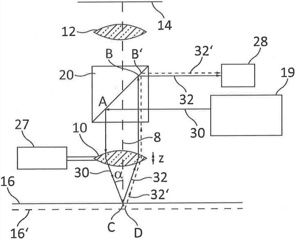
[0045] Fig. 1 shows a triangularized self-focusing device according to the prior art US5136149B1, which has been described in detail in conjunction with a particularly advantageous embodiment of the present invention.

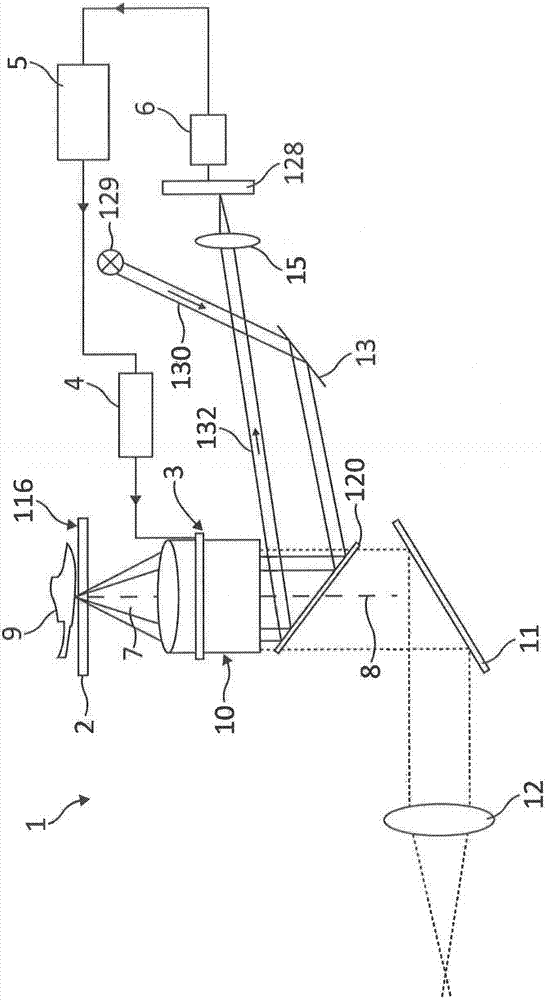
[0046] figure 2 A preferred embodiment of the device according to the invention for determining spherical aberration in microscopic imaging of a microscope 1 is schematically shown, wherein only necessary components (to be described below) are shown. The sample 9 is placed on the cover glass 2 carrying the sample 9 . The cover glass 2 is placed in the imaging optical path 7 of the microscope 1 . Microscope objectives are numbered 10. The tube lens 12 is only schematically drawn. Other details such as eyepieces, image acquisition detectors, zoom systems etc. are not shown as they are not essential to the invention. These units are known to those skilled in the art from the prior art.

[0047] Sample 9 may involve live cells that are observed over a longer p...


PUM


Abstract

A method and apparatus provide identification of a spherical error of a microscope imaging beam path in a context of microscopic imaging of a sample using a microscope having an objective. A coverslip that carries or covers the sample is arranged in the imaging beam path. A measurement beam is guided through the objective onto the sample in a decentered fashion that is outside an optical axis of the objective. The measurement beam is reflected at an interface of the coverslip with the sample and the reflected measurement beam is guided through the objective onto a detector. An intensity profile of the reflected measurement beam is detected with the detector and a presence of a spherical error from the intensity profile is determined qualitatively and/or quantitatively.

Description

technical field [0001] The invention relates to a device and a method for determining and correcting spherical aberration in microscopic imaging. A microscope including an objective lens is used to perform microscopic imaging of a sample, and a cover glass carrying the sample or covering the sample is arranged in the imaging optical path of the microscope. Background technique [0002] For microscopic analysis, the sample to be analyzed is usually placed above or below a coverslip, or into a large-area sample chamber (well plate, microtiter plate, Labtech plate). There are a variety of coverslip thicknesses. In particular, in the aforementioned sample chamber, the thickness of the cover glass fluctuates significantly. Variations in the thickness of the coverslip can negatively affect the optical performance of the system when the coverslip is placed in the imaging optical path. In imaging using large sample chambers, variations in cover glass thickness lead to impaired ima...

Claims


Application Information

Patent Timeline
Patent Type & Authority Applications(China)
IPC IPC(8): G02B21/24G02B27/00
CPCG02B21/241G01M11/02
Inventor W·奈彼尔T·鲍尔P·尤特诺伊尔
Owner LEICA MICROSYSTEMS CMS GMBH
Why Eureka
Try Eureka