Novel liquid crystal module structure

A liquid crystal module, a new type of technology, applied in lighting devices, optics, instruments, etc., can solve the problems of cumbersome assembly process, time-consuming and laborious, and achieve the effects of quick installation, reduced labor intensity, and improved production efficiency

Active Publication Date: 2013-04-17
SUZHOU VICTORY PRECISION MFG
View PDF6 Cites 6 Cited by
  • Summary
  • Abstract
  • Description
  • Claims
  • Application Information

AI Technical Summary

Problems solved by technology

[0002]The traditional liquid crystal module consists of a backlight module, a front case, and a rear case. During the assembly proces

Method used


Image

  • Novel liquid crystal module structure
  • Novel liquid crystal module structure
  • Novel liquid crystal module structure

Examples


Example Embodiment

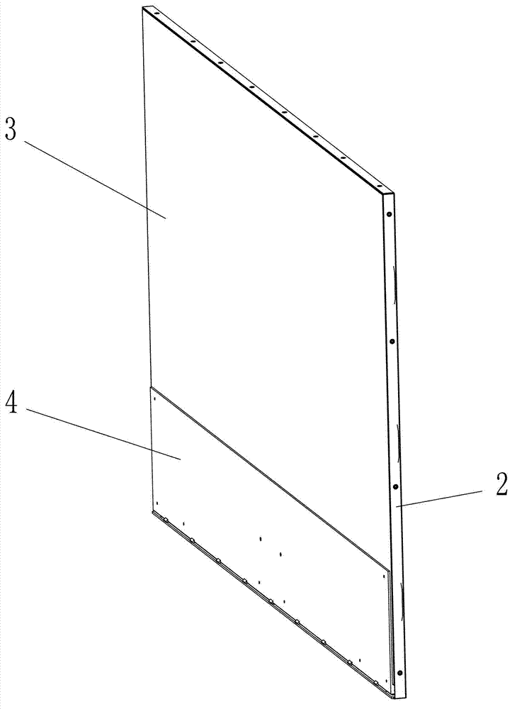
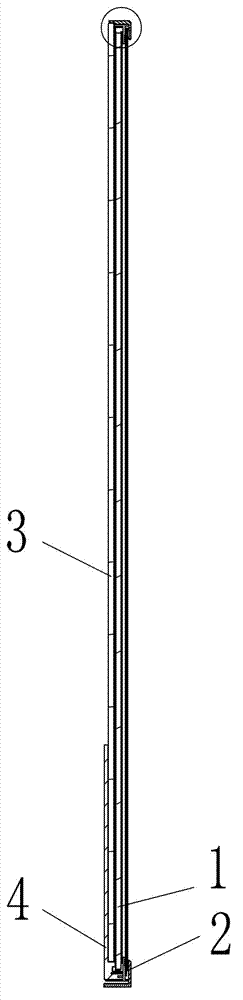
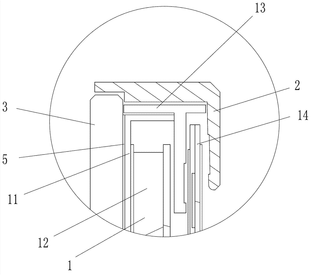
[0018] Example: as Figure 1 to Figure 4 As shown, a new type of liquid crystal module structure includes a backlight module 1, a front case 2 and a back plate 3, the back plate 3 is a glass back plate, the glass back plate 3 and the metal frame 11 of the liquid crystal module 1 Adhesive and fixed, the front case 2 covers the outer periphery of the liquid crystal module 1, and the side of the front case 2 and the outer periphery of the metal frame 11 are screwed and fixed by screws, and the plastic frame 13 of the liquid crystal module 1 is provided with screws for screws For the through holes, the side edges of the front shell 2 are screwed and fixed to the metal frame 11 through the holes of the plastic frame 13 through screws. The bottom of the rear side of the back plate 3 is glued and fixed with a heat sink 4 .

[0019] The above-mentioned metal frame 11 and the heat dissipation plate 4 can be attached to the back plate by using glue, tape or other adhesives 5 .

[...


PUM


Abstract

The invention discloses a novel liquid crystal module structure. The novel liquid crystal module structure comprises a backlight module, a front shell and a back plate, the back plate is fixedly adhered with a metal frame of the backlight module, the front shell covers the periphery of the backlight module, and the side edges of the front shell are fixedly connected with the periphery of the metal frame. The back plate is directly fixed on the backlight module by means of adhesion of the back plate with the metal frame of the backlight module, the novel liquid crystal module structure is assembled only by screw joint of the front shell with the metal frame and is quite rapid to mount, labor intensity is reduced greatly, and production efficiency is improved.

Description

technical field [0001] The invention relates to a liquid crystal module structure. Background technique [0002] The traditional liquid crystal module consists of a backlight module, a front case, and a rear case. During the assembly process, the front case and the backlight module need to be fixed by a lot of screws respectively. The assembly process is cumbersome and time-consuming. Contents of the invention [0003] The purpose of the present invention is to provide a new type of liquid crystal module structure, which uses the method of bonding the back plate and the metal frame of the liquid crystal module, so that the back plate is directly fixed on the backlight module, and only the front shell and the front shell need to be screwed during assembly. The metal frame is enough, and the installation is very fast, which greatly reduces the labor intensity and improves the production efficiency. [0004] The technical solution of the present invention is: a novel liquid ...

Claims


Application Information

Patent Timeline
IPC IPC(8): G02F1/13G02F1/13357F21V17/10
Inventor 焦宪友
Owner SUZHOU VICTORY PRECISION MFG
Why Eureka
Try Eureka