Thermal-insulating device of thermal control system of aerial camera

A technology of heat insulation device and thermal control system, which is applied in the direction of camera, camera body, optics, etc., can solve the problem of difficult control of heat loss of controlled components, reduce the heat leakage rate of optical system, and reduce the thermal resistance of heat insulation structure and other problems, to achieve the effect of adjustability, high reliability, and increase the thermal resistance of the heat insulation structure

Inactive Publication Date: 2013-04-17
INST OF OPTICS & ELECTRONICS - CHINESE ACAD OF SCI
View PDF6 Cites 5 Cited by
  • Summary
  • Abstract
  • Description
  • Claims
  • Application Information

AI Technical Summary

Problems solved by technology

[0005] In order to solve the technical problems of reducing the thermal resistance of the heat insulation structure due to the high thermal conductivity of the screw connection material in the existing heat insulation structure, and the heat loss of the controlled component is difficult to control, the purpose of the present i

Method used


Image

  • Thermal-insulating device of thermal control system of aerial camera
  • Thermal-insulating device of thermal control system of aerial camera
  • Thermal-insulating device of thermal control system of aerial camera

Examples


Embodiment Construction

[0011] In order to make the object, technical solution and advantages of the present invention clearer, the present invention will be described in further detail below in conjunction with specific embodiments and with reference to the accompanying drawings.

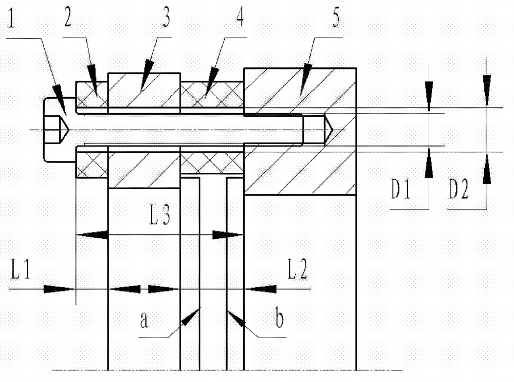
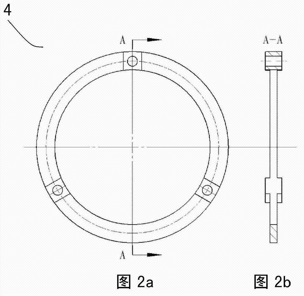
[0012] Such as figure 1 The heat insulation structure of the thermal control system of an aerial camera is shown, including three stainless steel screws 1, three heat insulation washers 2, and heat insulation pads 4, as well as the first structural member 3 and the second structural member 5, of which: 3 The stainless steel screw 1 and three heat insulating washers 2 are symmetrically distributed along the axial direction; the heat insulating pad 4 is located between the first structural member 3 and the second structural member 5; the heat insulating washer 2 is located in the ring of the stainless steel screw 1 Between the shape surface and the plane of the first structural member 3; the heat insulating gasket 2, the fi...


PUM

PropertyMeasurementUnit
Elastic modulusaaaaaaaaaa

Abstract

The invention relates to a thermal-insulating device of a thermal control system of an aerial camera. The thermal-insulating device comprises three stainless steel bolts and three thermal-insulating gaskets, which are symmetrically distributed along the axial direction, wherein a circular thermal-insulating pad is arranged between a first structure element and a second structure element; the thermal-insulating gaskets are arranged between an annular surface of each stainless steel bolt and a plane of the first structure element; the thermal-insulating gaskets, the first structure element, the thermal-insulating pad and the second structure element are fixedly connected through the stainless steel bolts; three symmetrically distributed bosses respectively extend from the first end face and the second end face of the thermal-insulating pad; the surfaces of three bosses at the first end face contact the plane of the first structure element; the surfaces of three bosses at the second end face contact the plane of the second structure element; a connection section of the stainless steel bolts penetrates through a through hole at the center of each boss; the boss structure is used for increasing the heat resistance and the contact heat resistance of the thermal-insulating pad; the heat of the first structure element is isolated through the thermal-insulating pad and the thermal-insulating gaskets; the heat is prevented from being directly transmitted to the second structure element from the first structure element; and the heat is also prevented from being conducted through the stainless steel bolts.

Description

technical field [0001] The invention relates to a thermal insulation structure of an aerial camera thermal control system, which is suitable for the thermal control field of aerospace equipment. Background technique [0002] Aerial cameras are precision optical instruments mounted on aircraft to capture ground objects by taking pictures of the surface. For cameras working at high altitudes, the ambient temperature will change greatly from the ground to the high altitude. Due to the thermal instability of optical materials and structural materials, temperature changes may cause the system to defocus, resulting in wavefront distortion, resulting in imaging The quality deteriorates. In order to meet the high-resolution requirements of aerial cameras, certain thermal control measures must be taken to ensure high-quality images. [0003] Thermal control measures include passive thermal control and active thermal control. Generally, the thermal control system is designed accordi...

Claims


Application Information

Patent Timeline
IPC IPC(8): G03B17/56G03B17/55
Inventor 樊越梁伟马文礼赵人杰
Owner INST OF OPTICS & ELECTRONICS - CHINESE ACAD OF SCI
Why Eureka
Try Eureka