Switching power supply and controller thereof

A technology of switching power supply and controller, which is applied in the direction of conversion equipment with intermediate conversion to AC, irreversible conversion of AC power input into DC power output, etc. It can solve the problems of slow loop response, low power factor, and slow start. Achieve the effect of accelerating the startup speed, fast loop response speed, and preventing bad startup

Active Publication Date: 2013-04-17
HANGZHOU SILAN MICROELECTRONICS
View PDF5 Cites 16 Cited by
  • Summary
  • Abstract
  • Description
  • Claims
  • Application Information

AI Technical Summary

Problems solved by technology

When the input voltage Vin is low, due to the low initial output energy at startup, the loop response is slow, and the startup is very slow. After startup, the VCC capacitor 105 is discharged, and when the VCC capacitor 105 is discharged to the shutdown voltage V1, if the output voltage has not yet been established, then It is easy to fail to start at one time, resulting in poor startup
When the input voltage Vin is high, due to the large initial output energy, the loop response is slow, which may easily lead to overshoot of the output voltage during startup, which affects the safety of the circuit.
On the other hand, if a smaller compensation capacitor 113 is used, although the establishment of the loop at startup can be accelerated, the power factor will be lower after normal operation, and the stability of the circuit will deteriorate

Method used


Image

  • Switching power supply and controller thereof
  • Switching power supply and controller thereof
  • Switching power supply and controller thereof

Examples


Embodiment Construction

[0046] The present invention will be further described below in conjunction with specific embodiments and accompanying drawings, but the protection scope of the present invention should not be limited thereby.

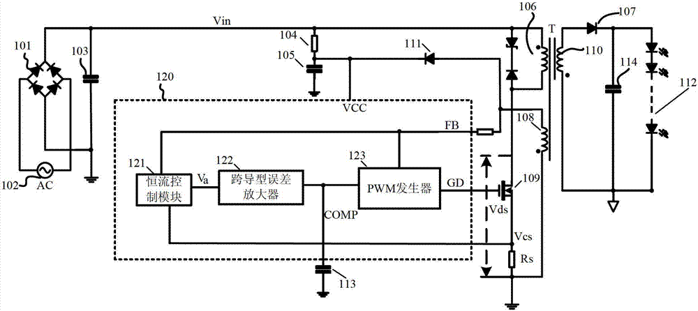
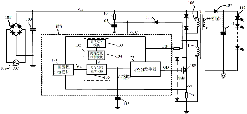
[0047] refer to image 3 , image 3 The circuit structure of the flyback switching power supply of the first embodiment is shown, which adopts a constant current control loop. The switching power supply includes: input rectifier bridge 101, AC source 102, input filter capacitor 103, start-up resistor 104, VCC capacitor 105, flyback transformer T (including primary winding 106, secondary winding 110 and auxiliary winding 108), output rectifier Diode 107 , output capacitor 114 , power tube 109 , sampling resistor Rs, output light-emitting diode 112 , output winding power supply rectifier diode 111 , and controller 130 . Wherein, the connection mode and working principle of other components except the controller 130 are the same as the conventional switching power suppl...


PUM


Abstract

The invention provides a switching power supply and a controller thereof. The controller comprises a constant current / constant voltage control module, a subdivision control type error amplifier and a PWM (pulse-width modulation) generator, wherein the constant current / constant voltage control module is used for detecting an output constant current value / an output constant voltage value of the switching power supply, and converting the output constant current value / the output constant voltage value into an equivalent value; the subdivision control type error amplifier is connected with the constant current / constant voltage control module to carry out error amplification on the equivalent value and a preset reference value, and the trans-conductance or the magnification time of the subdivision control type error amplifier are gradually reduced within two or more continuous time buckets after a circuit is started; and the PWM generator is connected with an output end of the subdivision control type error amplifier, the duty ratio of a driving signal is confirmed according to an output signal of the subdivision control type error amplifier, and the driving signal is used for driving a power tube of the switching power supply. According to the witching power supply and the controller, the quick start of the circuit can be realized, the overshoot of output voltage / current can be avoided, and the characteristic of the circuit can not be influenced when the circuit stably works on the premise that the VCC (virtual channel connection) capacitance power supply time is not prolonged.

Description

technical field [0001] The invention relates to switching power supply technology, in particular to a fast-start switching power supply and a controller thereof. Background technique [0002] figure 1 It shows a traditional flyback single-stage LED drive power supply with a transconductance amplifier, including: input rectifier bridge 101, AC source 102, input filter capacitor 103, startup resistor 104, VCC capacitor 105, flyback transformer T, output Rectifier diode 107 , output capacitor 114 , output LED 112 , power tube 109 , sampling resistor Rs, auxiliary winding power supply rectifier diode 111 , and controller 120 . [0003] The flyback transformer T includes a primary winding 106 , a secondary winding 110 and an auxiliary winding 108 . [0004] The controller 120 includes: a constant current control module 121, which detects the output constant current value according to the voltage on the sampling resistor Rs and the output signal FB generated by the auxiliary win...

Claims


Application Information

Patent Timeline
Patent Type & Authority Applications(China)
IPC IPC(8): H02M7/12H02M3/28
Inventor 姚云龙吴建兴
Owner HANGZHOU SILAN MICROELECTRONICS
Why Eureka
Try Eureka