Supercharge Your Innovation With Domain-Expert AI Agents!

Split architecture remote radio

一种射频拉远头、无线通信系统的技术,应用在无线通信、网络流量/资源管理、电气元件等方向,能够解决不能部署光纤电缆、成本昂贵、高成本和费用等问题

Inactive Publication Date: 2013-04-17
AVAGO TECH INT SALES PTE LTD
View PDF6 Cites 8 Cited by
  • Summary
  • Abstract
  • Description
  • Claims
  • Application Information

AI Technical Summary

Problems solved by technology

However, fiber optic cables cannot be deployed or are very expensive to deploy in certain areas such as densely populated areas and areas with unusual topography
For example, deploying fiber in such areas would require excavating the ground and / or moving buildings embedded in these areas, all of which would be very costly and expensive
In addition, due to various reasons, it takes a long time to complete the fiber deployment

Method used


Image

  • Split architecture remote radio
  • Split architecture remote radio
  • Split architecture remote radio

Examples


Embodiment Construction

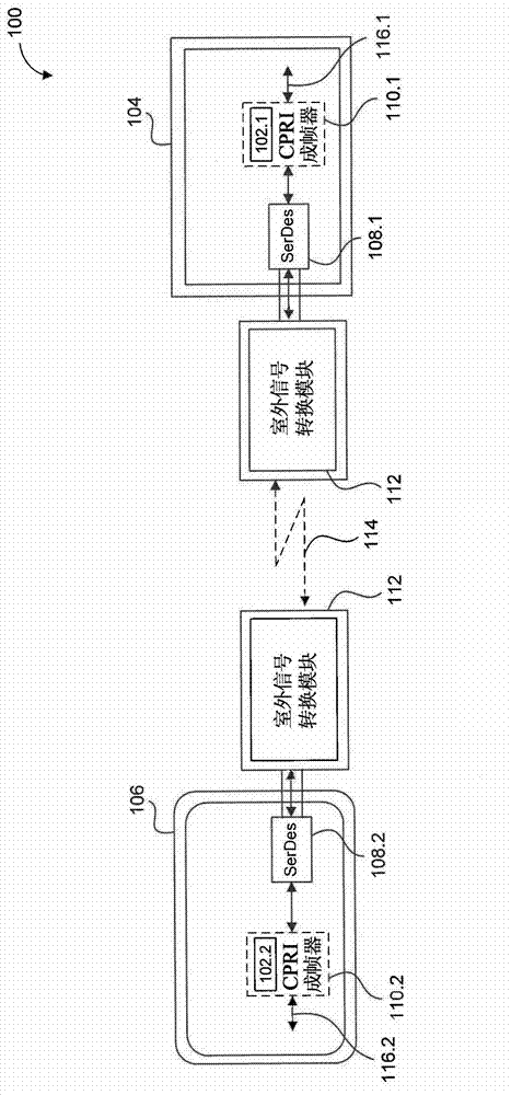
[0037] However, due to the higher bit rate requirements, fiber optic cables are used for communication between the base station and the Remote Radio Head (RRH). Fiber optic cables are connected directly between the base station and the RRH, allowing the strict timing requirements required by the standards governing communications over the link. However, fiber optic cables cannot be deployed in certain areas (dense population, unusual terrain, etc.) or are very expensive to deploy (requires digging the ground, moving buildings, etc.), resulting in very high fees / cost. In addition, it takes a long time to deploy fiber. Therefore, deploying fiber optic cables requires replacements.

[0038] The following detailed description sets forth exemplary embodiments consistent with the present invention with reference to the accompanying drawings. References in the detailed description to "one exemplary embodiment," "exemplary embodiment," "example exemplary embodiment," etc., indicat...


PUM


Abstract

A wireless communication system, which includes at least one base station module configured to implement a media access controller and a physical layer, and includes at least one remote radio head module configured to prepare an analog signal or a digital data signal for transmission and receipt over a link in accordance with dedicated interface specifications, and also includes at least one outdoor signal conversion module configured to perform a high rate digital-to-analog conversion and a high rate analog-to-digital conversion in accordance with the dedicated interface specifications, and further includes at least two millimeter wave antenna assemblies, where each antenna assembly is configured to transmit and receive the analog signal over a wireless link in accordance with the dedicated interface specifications.

Description

[0001] References to related applications [0002] This patent application claims priority to U.S. Provisional Patent Application No. 61 / 546,795, filed October 13, 2011, and U.S. Patent Application No. 13 / 344,016, filed January 5, 2012, which are incorporated by reference in their entirety In this article. technical field [0003] The present invention relates to millimeter wave point-to-point communications, and more particularly, to modem components. Background technique [0004] Radio Access Networks (RANs) are known components of various communication systems. The term "RAN" is generally used to denote the interface between a communication device and its Core Network (CN). In recent years, certain concepts have been introduced in an effort to reduce the capital expenditure and operating costs incurred in implementing and maintaining communication systems using the RAN. [0005] Such a concept is called "cloud radio access network" concept. In a common network archite...

Claims


Application Information

Patent Timeline
Patent Type & Authority Applications(China)
IPC IPC(8): H04W88/08
CPCH04W88/085H04W16/18H04W28/0861H04L12/46
Inventor 埃兰·里德尔兰·索菲尔
Owner AVAGO TECH INT SALES PTE LTD
Features
  • R&D
  • Intellectual Property
  • Life Sciences
  • Materials
  • Tech Scout
  • Unparalleled Data Quality
  • Higher Quality Content
  • 60% Fewer Hallucinations
Learn More