
Scanning backlight with slatless light guide

A backlight and light source technology, applied in such displays and backlights, related products, and systems, can solve problems such as image crosstalk

Inactive Publication Date: 2016-02-10
3M INNOVATIVE PROPERTIES CO
View PDF9 Cites 0 Cited by
  • Summary
  • Abstract
  • Description
  • Claims
  • Application Information

AI Technical Summary

Problems solved by technology

If the backlight is uniformly modulated between the left-eye and right-eye transmit beams across the output area of ​​the backlight, crosstalk may occur in some parts of the image

Method used


Image

  • Scanning backlight with slatless light guide
  • Scanning backlight with slatless light guide
  • Scanning backlight with slatless light guide

Examples


example

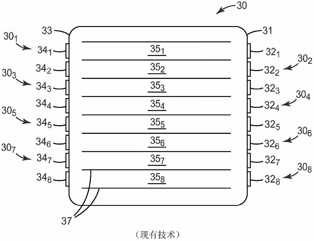
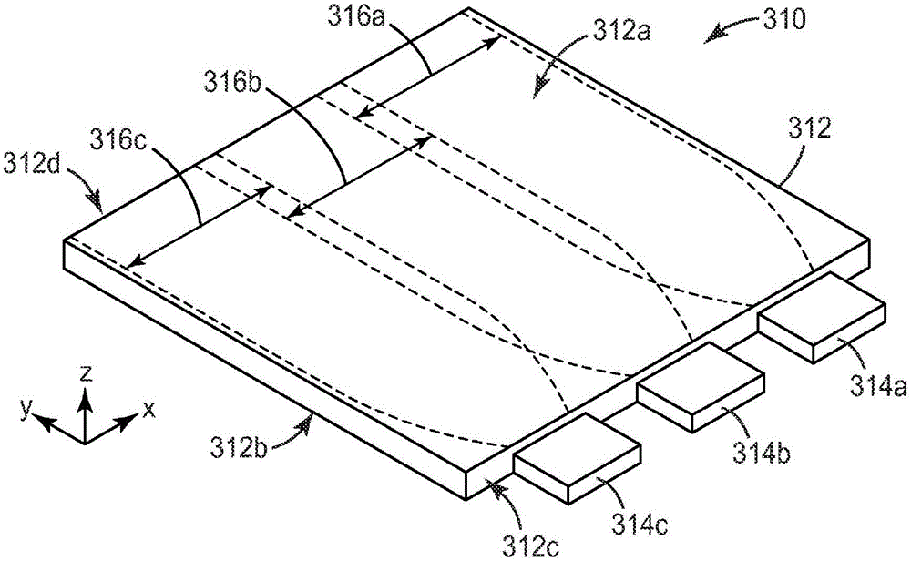
[0058] Construct similar to Figure 3b The scanning backlight is shown. The light guide was slatless, constructed of unit cast acrylic, and had a length of about 260 mm, a width of about 123 mm, and a thickness of about 3.2 mm. On the two opposite short sides of the light guide (sides with a dimension of 123mm) place a light source assembly with eight partially collimated light sources similar to a combined Image 6 with Figure 7a Examples shown and described. One light source assembly produces a right eye beam and the other light source assembly produces a left eye beam. All sixteen light sources are individually addressable so that any light source or combination of light sources can be energized as required. The base of the light source assembly (see Image 6 Item 609 in ) is a machined one-piece aluminum base with a nominal parabolic surface for each light source (see Image 6 item 614 in ). Parabolic surfaces usually fit the equation y=(0.25)*x 2 , where x and y ...


PUM

PropertyMeasurementUnit
lengthaaaaaaaaaa
widthaaaaaaaaaa
thicknessaaaaaaaaaa

Abstract

The present invention relates to a backlight comprising a light guide and a first light source and a second light source, the first and second light sources being adapted to operate independently and arranged to inject light into different parts of the surface, respectively, by injecting light into different parts of the surface. The first light beam and the second light beam are injected into the light guide. Each light source includes a lamp and a concave reflector to partially collimate light from the lamp. One major surface of the light guide includes prismatic structures parallel to the first axis. The other major surface of the light guide includes lens structures parallel to each other but perpendicular to the prismatic structures. The lens structure limits the spatial diffusion of light retained in the light guide. Each light source cooperates with the light guide to provide light that is substantially laterally confined to the transverse strips of the light guide, even if the light guide does not contain gaps for defining slats to achieve such confinement.

Description

technical field [0001] The present invention relates generally to backlit displays, with particular application to such displays and backlights that provide distinct left and right eye images to allow stereoscopic viewing. The invention also relates to related articles, systems and methods. Background technique [0002] Stereoscopic displays typically present the viewer with images with parallax from separate right and left eye viewpoints. There are several techniques to provide parallax images to both eyes of a viewer in order to create a stereoscopic viewing experience. In the first technique, the viewer uses a pair of shutter or three-dimensional ("3D") glasses that alternate left / right image displays while transmitting or blocking light from the viewer's view. In the second technique, right- and left-eye images are displayed alternately and directed toward the viewer's corresponding eye, but 3D glasses are not used. This second technique, known as autostereoscopic, fa...

Claims


Application Information

Patent Timeline
Patent Type & Authority Patents(China)
IPC IPC(8): G02F1/13357G02B27/22G02F1/1333G02B30/27
CPCG02B6/0028G02B6/0031G02B6/0038G02B6/0068G02B6/0091H04N13/32G02B30/27G02F1/1335
Inventor 埃里克·A·阿霍约翰·C·舒尔茨
Owner 3M INNOVATIVE PROPERTIES CO
Learn More