Combined sliding block forming mechanism of cavity die

A technology of combining sliders and cavities, applied in the field of combined slider forming mechanisms, can solve the problems of increasing mold development costs, unbalanced forming pressure, and the influence of the number of slider forming cavities, saving mold development costs and ensuring assembly. Accuracy, the effect of shortening the development cycle

Active Publication Date: 2015-05-13
浙江博毅云华医疗器械有限公司
View PDF1 Cites 0 Cited by
  • Summary
  • Abstract
  • Description
  • Claims
  • Application Information

AI Technical Summary

Problems solved by technology

[0004] 1. Due to the large heat treatment deformation, heat treatment is generally not carried out after processing, so that the strength of the formed parts is low and the wear resistance is also poor, which affects the service life of the mold
[0005] 2. The structural form is an integral type. When the cavity is partially or multi-cavity formed, individual cavities are damaged or worn, deformed, and the size is out of tolerance and cannot be repaired. The entire slider part can only be scrapped. One less production method, but it will easily lead to unbalanced forming pressure and affect the forming quality of other cavities
[0006] 3. Integral cavity processing is labor-intensive and time-consuming for clamping, forming, and measuring in the process flow, and it is easy to cause cumulative errors. Due to the limitation of process conditions, the number of forming cavities of the slider is also affected to a certain extent.
[0007] 4. In order to meet the forming quality requirements of the parts, the formed parts need high-quality steel with high performance requirements. The overall slider structure must use high-quality steel like the cavity, resulting in waste of steel and increased manufacturing costs of the mold.
[0008] 5. The cavity and the slider are integrated, and the versatility is not strong, so it can only be processed by a single piece. When forming the same series of parts with different structures, it is necessary to develop molds with different structures separately, which not only increases the development cycle of the mold, but also increases Mold development cost

Method used


Image

  • Combined sliding block forming mechanism of cavity die
  • Combined sliding block forming mechanism of cavity die
  • Combined sliding block forming mechanism of cavity die

Examples


Embodiment Construction

[0045] The present invention will be described in further detail below in conjunction with the accompanying drawings.

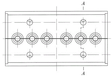
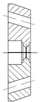
[0046] A combined slide block forming mechanism of a cavity mold of the present invention is shown in the appendix image 3 to attach Figure 11 , on the slider seat 1 corresponding to the two sides of the cavity block 2, the mounting holes for the positioning blocks 3 on both sides are opened, and the mounting holes for the positioning block 4 at the end are opened at the end, and the positioning blocks are lightly fitted with the corresponding mounting holes, and the cavity The block and slider seat are installed and positioned through the positioning block. The shape of the cavity block and the positioning block adopt H7 / k7 transition fit. Since the slider only bears the lateral parting force when the mold is opened and closed, the cavity block and the slider The light press fit of the seat eliminates the need for screw fixing and pin positioning.

[004...


PUM


Abstract

The invention discloses a combined sliding block forming mechanism of a cavity die. The combined sliding block forming mechanism comprises a sliding block seat and a cavity block, two side locating blocks, end-part locating blocks and locating block mounting holes which are formed on the sliding block seat and correspond to the positions at two sides and the end parts of the cavity block, wherein the two side locating blocks and the end-part locating blocks are respectively matched with the locating block mounting holes in a slight pressing way; and the cavity block is assembled and located on the sliding block seat through the locating blocks. The sliding block seat, the locating blocks and the cavity block are respectively machined and assembled; each workpiece can be thermally treated. Through thermal treatment, the strength and the wearing resistance of the parts are improved, the service life is obviously prolonged; multiple-cavity forming can be realized, the production efficiency is improved, a certain cavity block can be separately adjusted and replaced when the cavity block is worn and damaged and oversized; the exhaust performance is improved when the cavity die is formed; and the same series of cavity blocks in different structures are mounted and used in a size range, thus the development cycle of a die is shortened, and the development expense of the die is saved.

Description

technical field [0001] The combined sliding block forming mechanism of the cavity mold of the present invention is suitable for the design and application of the cavity mold forming parts of side-to-side paired Huff block core pulling. Background technique [0002] When forming coil skeleton parts and grooved pulley parts with a cavity mold, the cavity structure generally adopts side-to-side Huff blocks, and the demoulding action is completed through a side-parting core-pulling mechanism. [0003] The structure of the sidewise paired Huff block that has been used at present is as shown in the attachment of the instruction manual. figure 1 , manual attached figure 2 shown. The structure that the cavity and the slider are integrated has the following disadvantages: [0004] 1. Due to the large heat treatment deformation, heat treatment is generally not carried out after processing, so that the strength of the formed parts is low and the wear resistance is also poor, which...

Claims


Application Information

Patent Timeline
Patent Type & Authority Patents(China)
IPC IPC(8): B29C33/44
Inventor 江昌勇姜伯军
Owner 浙江博毅云华医疗器械有限公司
Why Eureka
Try Eureka