Car frame

A vehicle frame and underframe technology, applied in the field of vehicle underframe design, can solve the problems of poor handling, reduced transmission efficiency, high fuel consumption, etc., and achieve the effects of strong climbing ability, increased load capacity, and stable operation

Inactive Publication Date: 2013-04-24
GUANGXI HAOGANG MACHINERY
View PDF6 Cites 1 Cited by
  • Summary
  • Abstract
  • Description
  • Claims
  • Application Information

AI Technical Summary

Problems solved by technology

Existing agricultural tractors use a welded rigid connection between the front axle and the frame, which makes it easy to generate impact when the tractor is running on an uneven road surface, causing the vehicle to fail to absorb vibration, and affecting the driver's driving comfort and The stability of the vehicle climbing, the tractors of the existing tractors are not optimal within the national standard, the tractors are too large, the relative angle between the tractors and the chassis of the carriage is large, and the turning radius of the tractor is relatively large. It is not conducive to the flexible turning of vehicles when driving on narrow roads. At the same time, due to the low transmission efficiency of the transmission system, the work efficiency is low. At the same time, the cost is high, the fuel consumption is large, the reliability is not good, and the use economy is very poor. The main reasons are: The front axle is integrated with the transmission, the structure is complex, and the transmission efficiency is reduced. The front axle does not have brakes, the braking effect is not good, the safety is poor, and the controllability is poor. Two transmissions are needed to realize the synchronization of a certain gear, which adds a transmission. Cost, the cost increases, at the same time, the climbing ability is not strong, the load capacity is not large, and the driving stability on bad roads is not good
The transmission system is complicated, the fuel consumption is high, the economy is poor, and the overall performance is poor

Method used


Image

  • Car frame
  • Car frame

Examples


Embodiment Construction

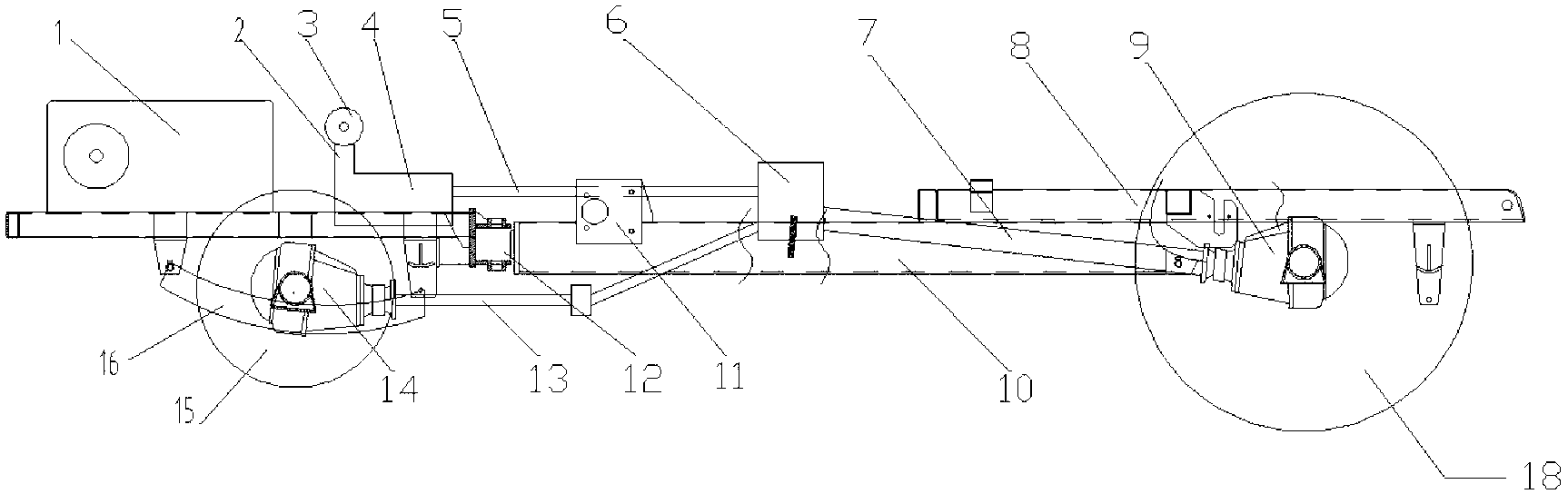
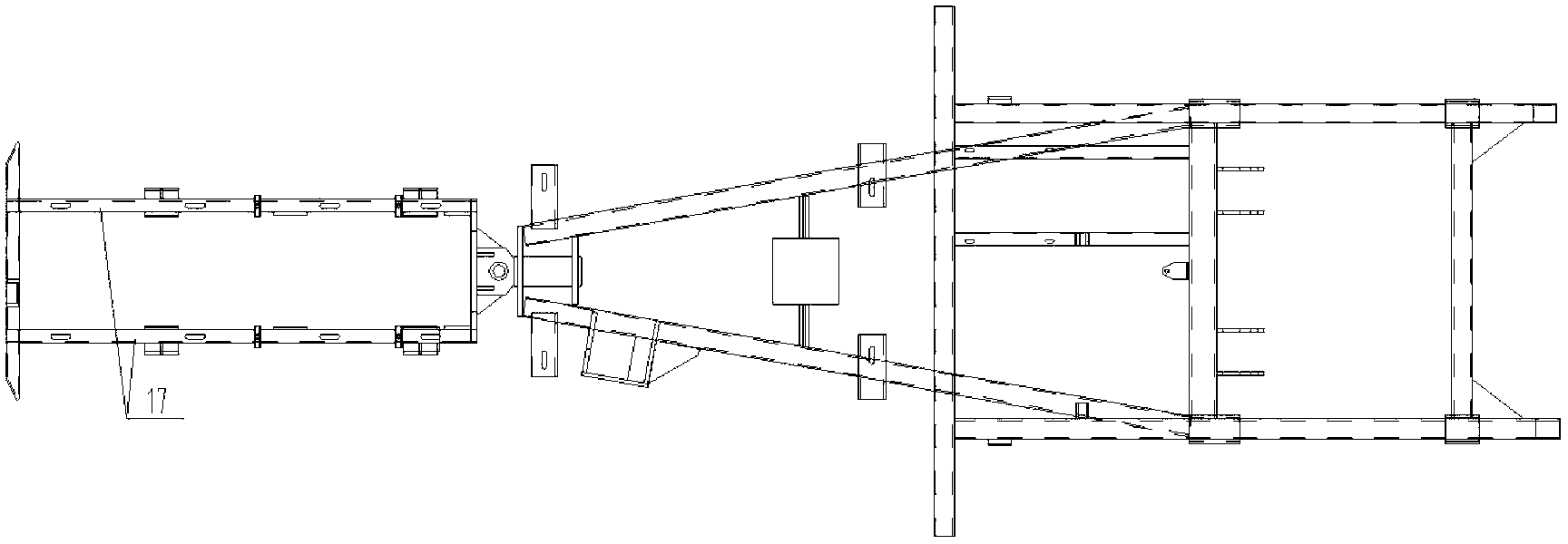
[0018] The frame includes left and right longitudinal beams (17), leaf springs (16), tractor (12), cab underframe (10) and rear underframe (8); wherein, the leaf springs (16) are Bow-shaped structure, fixed brackets and fixed underframes are respectively provided at the front and back of the bending point, and the fixed brackets and fixed underframes fix the leaf springs (16) on the left and right longitudinal beams (17); the left and right longitudinal beams (17) are respectively connected with cross beams at the front and rear , the rear beam is fixedly connected with the tractor (12); the tractor (12) can rotate horizontally, the rear of the tractor (12) is connected to the front of the cab chassis (10), and the rear of the cab chassis (10) The part is connected with the rear underframe (8).

[0019] Preferably, the front ends of the left and right longitudinal beams (17) are provided with an oil engine installation plate on which the engine is installed; the transmission (...


PUM


Abstract

A car frame comprises left and right longitudinal beams (17), a plate spring (16), a tractor (12), a cab underframe (10) and a rear underframe (8). The plate spring (16) is in a bow structure, and a fixed support and a fixed underframe are arranged in front and rear of a bowing point of the plates spring (16) respectively, the plate spring (16) is fixed on the left and right longitudinal beams (17) through the fixed support and the fixed underframe, the front and rear of the left and right longitudinal beams (17) are connected with transverse beams respectively, the rear transverse beam is fixedly connected with the tractor (12), the tractor (12) is capable of rotating horizontally, the rear of the tractor (12) is connected with the front of the cab underframe (10), and the rear of the cab underframe (10) is connected with the rear underframe (8).

Description

Technical field: [0001] The invention relates to the field of vehicle underframe design, in particular to a tractor head frame, which is especially suitable for agricultural tractors. Background technique: [0002] At present, agricultural mechanization is an important measure to solve the three rural issues and realize agricultural modernization. A considerable part of agricultural machinery is agricultural tractors, which are used for short-distance transportation and are currently one of the main means of transportation in rural areas. Existing agricultural tractors use a welded rigid connection between the front axle and the frame, which makes it easy to generate impact when the tractor is running on an uneven road surface, causing the vehicle to fail to absorb vibration, and affecting the driver's driving comfort and The stability of the vehicle climbing, the tractors of the existing tractors are not optimal within the national standard, the tractors are too large, the...

Claims


Application Information

Patent Timeline
IPC IPC(8): B62D21/02B60K5/12B60K17/04
Inventor 李易伦
Owner GUANGXI HAOGANG MACHINERY
Why Eureka
Try Eureka