
Air conveyor

A technology of pneumatic conveyors and cylinders, which is applied to conveyors, conveying bulk materials, transportation and packaging, etc., can solve the problems of simple way to supplement air source pressure, high transportation cost, and inability to replenish air, so as to avoid secondary pollution. , The effect of improving the conveying capacity and reducing the conveying cost

Inactive Publication Date: 2013-04-24
韩香莲
View PDF7 Cites 12 Cited by
  • Summary
  • Abstract
  • Description
  • Claims
  • Application Information

AI Technical Summary

Problems solved by technology

Its disadvantages are: during long-distance transportation, there is no barrier in the main transportation pipeline, and the method of supplementing the gas source pressure in the pipeline is simple and uncontrollable, and it is impossible to supplement the gas according to specific needs, which will cause waste of gas source. Higher delivery costs

Method used


Image

  • Air conveyor

Examples


Embodiment Construction

[0015] In order to clearly illustrate the technical features of the solution, the solution will be described below through a specific implementation mode combined with the accompanying drawings.

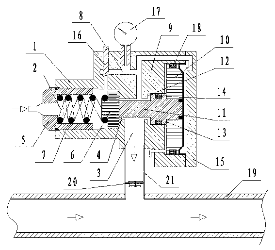
[0016] Such as figure 1 A pneumatic conveyor shown includes a body 1, the body 1 contains two chambers, an air inlet chamber 2 and an air outlet chamber 3, and an inner hole 4 communicates between the two chambers; one end of the air inlet chamber 2 is fixed with a A connecting pipe 5 connected to the main body 1; a valve plate 6 is provided at the inner hole, and a spring 7 for pressing the valve plate is arranged between the valve plate and the connecting pipe; a communication outlet is opened on the side wall of the air intake chamber 2 The drain hole 8 of the chamber 3; the body 1 also includes a cylinder, and the cylinder includes a cylinder body 9 integrated with the body, and the other end of the cylinder body 9 is equipped with a sealed end cover 15; a piston 10 is slidably a...


PUM


Abstract

The invention discloses an air conveyor which comprises a body. The body internally comprises an air inlet chamber and an air outlet chamber which are communicated through an inner hole, a connecting pipe connected with the body is fixed at one inner end of the air inlet chamber, a valve plate is arranged at the position of the inner hole, a spring for compacting the valve plate is arranged between the valve plate and the connecting pipe, and a flowing hole communicated with the air outlet chamber is arranged on the side wall of the air inlet chamber. The body further comprises the air cylinder, the air cylinder comprises a cylinder block integrated with the body, a sealed end cover is matched at the other end of the cylinder block, a piston is slidably arranged in the cylinder block and is connected with the valve plate through a connecting rod, an air inlet end of the air cylinder is communicated with the flowing hole through a through hole, and the cross section of the valve plate is smaller than the area of the piston. The air conveyor has the advantages that the air conveyor is capable of monitoring pressure conditions in a conveying pipeline in real time and capable of supplementing air to increase inlet air when the pipeline is blocked, so that conveying capability is improved, and conveying cost is reduced. The air conveyor is capable of achieving totally-closed material conveyance, and secondary contamination to materials is avoided.

Description

technical field [0001] The invention relates to a pneumatic conveying device applied to powder and granular materials, in particular to a device for replenishing gas source in a pneumatic conveying pipeline. Background technique [0002] In building materials, chemical industry, grain, metallurgy, environmental protection energy and other industries, for the transportation of powdery and granular materials, there are many augers and conveyor belts for conveying materials. In this way, the materials conveyed in the auger or the conveyor belt are exposed to the production environment. It will cause secondary pollution. In addition, in the transportation of powdery, granular and fibrous materials such as factories, workshops, buildings, roads, and railways, air supply pipes are also used to convey materials; when using traditional air supply pipes to convey materials, such as: cement, flour, Lime, coal powder, chemical fertilizer and other transportation operations are prone t...

Claims


Application Information

Patent Timeline
Patent Type & Authority Applications(China)
IPC IPC(8): B65G53/58
Inventor 韩香莲
Owner 韩香莲
Learn More