
Mechanical seal device of rotor pump

A mechanical sealing device, rotor pump technology, applied in mechanical equipment, rotary piston type/swing piston type pump parts, pump components, etc. The sealing effect and service life of the ring and the static ring can increase the sealing effect and service life, the cooling effect is good, and the cooling effect is increased.

Active Publication Date: 2013-04-24
NINGBO DELISHI PUMP IND CO LTD
View PDF7 Cites 3 Cited by
  • Summary
  • Abstract
  • Description
  • Claims
  • Application Information

AI Technical Summary

Problems solved by technology

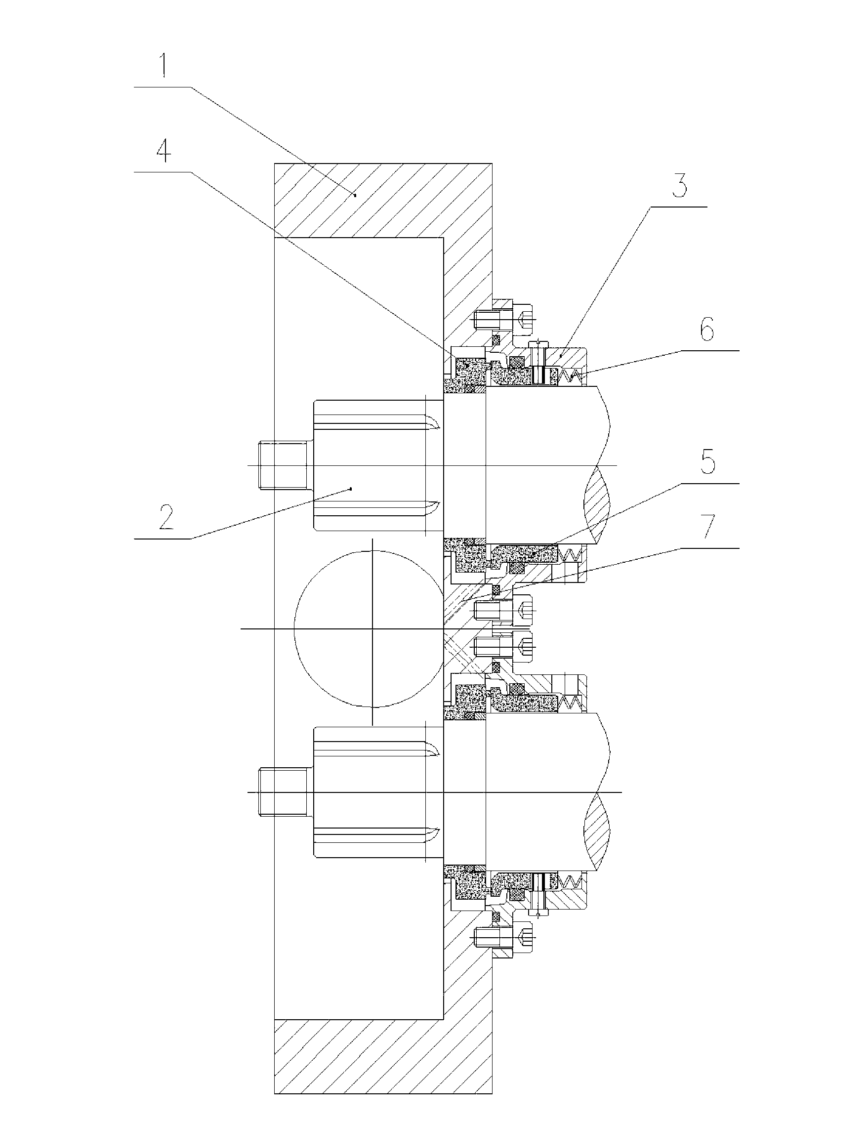
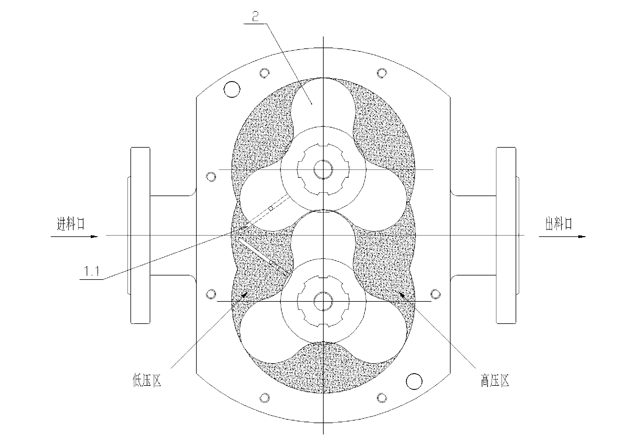
The mechanical seal device of the rotor pump with the above structure has the following disadvantages: after the transported medium enters the feed port, the low-pressure area of ​​the cavity containing the two rotors through the pump body passes through the action of the two rotors to the high-pressure area, and then It flows out from the discharge port, and at the same time, the conveyed medium will flow into the cavity between the movable ring and the pump body from the gap between the shaft hole wall of the pump body and the outer wall of the moving ring. The dynamic and static rings that play a sealing role have a large extrusion force, and long-term work will affect the sealing effect and service life of the dynamic and static rings
After the medium enters the cavity between the moving ring and the pump body, once it accumulates too much, it cannot circulate and continues to heat up, which reduces the cooling effect of the medium on the moving ring and the static ring.

Method used


Image

  • Mechanical seal device of rotor pump
  • Mechanical seal device of rotor pump

Examples


Embodiment Construction

[0011] The present invention will be further described below in conjunction with the accompanying drawings and specific embodiments.

[0012] Such as figure 1 , figure 2 As shown, the mechanical seal device of the rotor pump of the present invention includes a rotating shaft 2 arranged on the pump body 1, a sealing seat 3 fixed on the end surface of the pump body 1, and a shaft hole arranged in the shaft hole of the pump body 1 and around the rotating shaft 2. The moving ring 4 to limit, the static ring 5 and the spring 6 located outside the rotating shaft 2; 2 is stationary, the spring 6 is arranged outside the rotating shaft 2, one end is against the static ring 5, and the other end is against the inner end surface of the sealing seat 3, and the end surface of the static ring 5 is press-fitted on the moving ring 4 through the spring 6 On the end face: the cavity between the moving ring 4 and the pump body 1 communicates with the low-pressure area of ​​the cavity of the pu...


PUM


Abstract

The invention discloses a mechanical seal device of a rotor pump. The mechanical seal device of the rotor pump comprises a rotary shaft (2), a seal seat (3), a moving ring (4), a static ring (5) and a spring (6), wherein the rotary shaft (2) is arranged on a pump body (1); the seal seat (3) is fixed on the end surface of the pump body (1); the static ring (5) is arranged out of the rotary shaft (2); the static ring (5) is peripherally limited into the seal seat (3); the spring (6) is arranged out of the rotary shaft (2), one end of the spring (6) butts against the static ring (5), and the other end of the spring (6) butts against the inner end surface of the seal seat (3); the end surface of the static ring (5) is pressed and matched on the end surface of the moving ring (4) through the spring (6); and an empty cavity between the moving ring (4) and the pump body (1) is communicated with a low-pressure area of a cavity body of the pump body for containing two rotors through a backflow channel. The mechanical seal device of the rotor pump can increase the seal effect of the moving ring and the static ring and can prolong the service lives, and meanwhile also can increase the cooling effect to the moving ring and the static ring.

Description

technical field [0001] The invention relates to the technical field of rotor pumps, in particular to a mechanical seal device of a rotor pump. Background technique [0002] Rotor pumps use different sealing forms according to the medium to be transported. Generally speaking, packing seals are used for mediums with high viscosity and solidification at low temperatures, and mechanical seals are used for others. The mechanical seal device of the rotor pump is installed in the cavity where the rotating shaft protrudes from the pump body. Static ring and spring outside the rotating shaft; the moving ring is movably sleeved on the rotating shaft, inside the sealing seat of the circumferential limit of the static ring, the spring is arranged outside the rotating shaft, one end is against the static ring, and the other end Against the inner end surface of the sealing seat, the end surface of the static ring is press-fitted on the end surface of the moving ring through a spring. Th...

Claims


Application Information

Patent Timeline
Patent Type & Authority Applications(China)
IPC IPC(8): F04C15/00
Inventor 聂如国
Owner NINGBO DELISHI PUMP IND CO LTD
Learn More