Micro-bulge double-layer composite groove deep end surface mechanical seal structure

An end-face mechanical seal and double-layer composite technology, which is applied in the direction of engine seals, mechanical equipment, engine components, etc., can solve problems such as seal failure, achieve the effects of avoiding failure, preventing function failure, and enhancing the dynamic pressure effect

Active Publication Date: 2013-04-24
JINTUO PETROLEUM MACHINERY MANUFACTRING CO LTD
View PDF7 Cites 9 Cited by
  • Summary
  • Abstract
  • Description
  • Claims
  • Application Information

AI Technical Summary

Problems solved by technology

[0003] The invention aims to solve the problem of seal failure caused by the condensation of the gas film between the end faces due to the temperature drop in the non-contact gas seal, and provides a seal that can be applied to various working conditions, especially working conditions such as high pressure, low temperature, and critical phase change of the medium. Sealing face structure

Method used


Image

  • Micro-bulge double-layer composite groove deep end surface mechanical seal structure
  • Micro-bulge double-layer composite groove deep end surface mechanical seal structure
  • Micro-bulge double-layer composite groove deep end surface mechanical seal structure

Examples


Embodiment 1

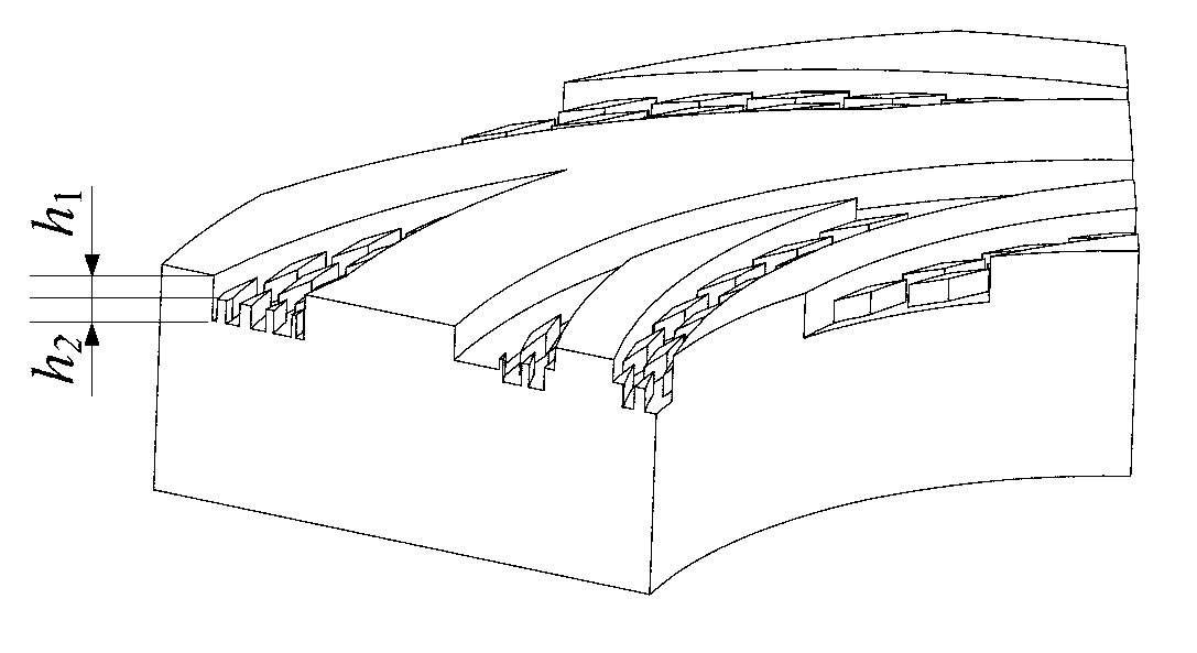
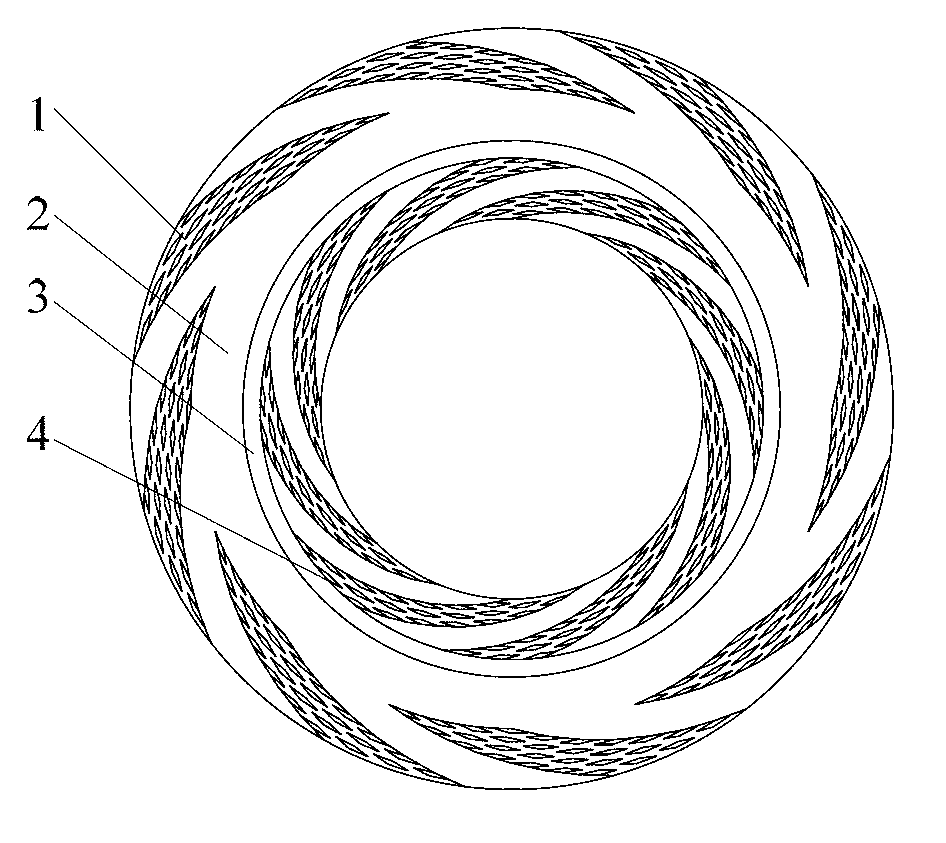
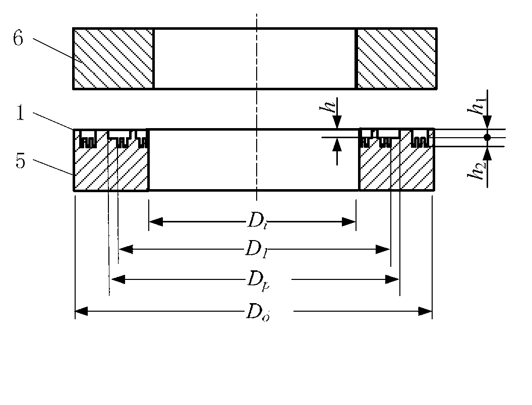
[0021] see Figure 1-3 : Micro-convex body double-layer composite groove deep end face mechanical seal structure, including mechanical seal dynamic ring 5, static ring 6, the mutual contact surface of the dynamic ring and the static ring is the end face, one of the end faces of the dynamic ring or the static ring is controlled by high pressure On the lateral low-pressure side, the asperity double-layer composite groove deep dynamic pressure groove 1, the sealing dam 2, the annular groove 3, the asperity double-layer composite groove deep pumping groove 4, and the dynamic pressure groove 1 arranged symmetrically according to the rotation center are arranged in sequence. It is connected with the ring groove 3 by the seal dam 2, and the seal dam 2 and the pumping groove 4 are connected by the ring groove 3;

[0022] Slightly convex double-layer composite groove Deep dynamic pressure groove 1 is set on the upstream side of the end face (high pressure side). The upper layer of the ...

Embodiment 2

[0031] see Figure 5 , 6 : Asperity double-layer composite groove deep end face mechanical seal structure, including mechanical seal dynamic ring 5, static ring 6, one of the end faces of the dynamic ring or static ring, from the high pressure side to the low pressure side are arranged in sequence according to the rotation center Symmetrical distribution Dynamic pressure groove 1, sealing dam 2, ring groove 3 and deep pumping groove 4 of micro-convex double-layer composite groove, dynamic pressure groove 1 and ring groove 3 are connected by sealing dam 2, sealing dam 2 and pumping groove 4 They are connected by ring groove 3;

[0032] The dynamic pressure groove 1 is set on the upstream side of the end surface (high pressure side). The dynamic pressure groove can be a spiral groove, T-shaped groove, circular micro-hole or inclined elliptical micro-hole and other end-face groove structures. The optimal value range of the groove depth is 2~ 10μm;

[0033] The remaining struct...


PUM


Abstract

The invention discloses a micro-bulge double-layer composite groove deep end surface mechanical seal structure which comprises a movable ring and a static ring. The movable ring and the static ring are mechanically sealed, a mutual contact surface of the movable ring and the static ring is an end surface, and a micro-bulge double-layer composite groove deep dynamical pressure groove, a sealing dam, a ring groove and a micro-bulge double-layer composite groove deep pumping groove which are symmetrically distributed along a rotation center are sequentially arranged on the end surface of the movable ring or the static ring from a high pressure side to a low pressure side; the dynamical pressure groove is arranged on the upstream (the high pressure side) of the end surface, and a micro-bulge body texture is processed on the lower layer of the dynamical pressure groove; the pumping groove is arranged on the downstream ( the lower pressure side) of the end surface, and a micro-bulge body texture is processed on the lower layer of the pumping groove; the inclining direction of the pumping groove is opposite to that of the dynamical pressure groove; the sealing dam is an unprocessed smooth plane; and the ring groove is communicated with the pumping groove and arranged on the upstream of the pumping groove.

Description

(1) Technical field [0001] The patent of the present invention relates to the technical field of end face mechanical seal design, specifically a double-layer composite groove deep end face mechanical seal structure composed of a dynamic pressure groove, a low-pressure pumping groove and a slightly convex structure at the bottom of the groove, which is suitable for various compressors, pumps, and steam turbines Shaft end seals for shafts of rotating machinery such as kettle stirrers. (2) Background technology [0002] Due to factors such as the drop of ambient temperature, the depth of the process medium, and the compressibility of the sealing gas, the temperature of the sealing gas film drops, causing the liquid phase of water vapor and other media to precipitate and adsorb on the sealing surface, destroying the stability of the sealing gas film, and eventually leading to seal failure. With the high parameterization of process equipment and the diversification of transport m...

Claims


Application Information

Patent Timeline
Patent Type & Authority Applications(China)
IPC IPC(8): F16J15/40F16J15/54
Inventor 白少先马春红彭旭东李纪云
Owner JINTUO PETROLEUM MACHINERY MANUFACTRING CO LTD
Why Eureka
Try Eureka