Method of temperature drift estimating and compensating in scanning probe microscopy

A technology of scanning probe and compensation method, applied in scanning probe technology, instruments, etc., can solve the problem of effectively calculating the temperature drift value, and achieve the effect of reducing human intervention and suppressing temperature drift

Inactive Publication Date: 2013-04-24
ZHEJIANG UNIV
View PDF2 Cites 14 Cited by
  • Summary
  • Abstract
  • Description
  • Claims
  • Application Information

AI Technical Summary

Problems solved by technology

[0005] In order to overcome the deficiency that the existing method cannot effectively calculate the temperature drift value when the temperature drift rate is constantly changing and the surface morphology of the sample is partially changed,

Method used


Image

  • Method of temperature drift estimating and compensating in scanning probe microscopy
  • Method of temperature drift estimating and compensating in scanning probe microscopy
  • Method of temperature drift estimating and compensating in scanning probe microscopy

Examples


Embodiment Construction

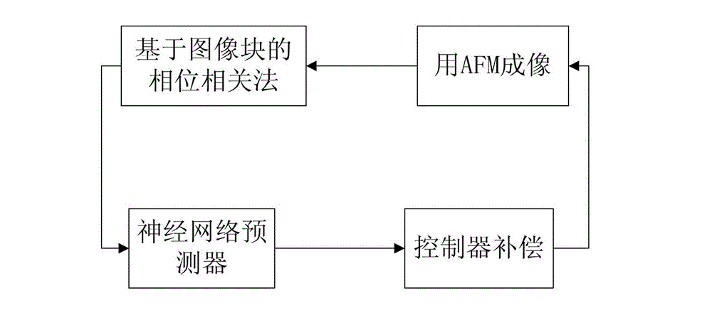
[0023] The method for estimating and compensating the temperature drift of the scanning probe microscope of the present invention comprises the following steps:

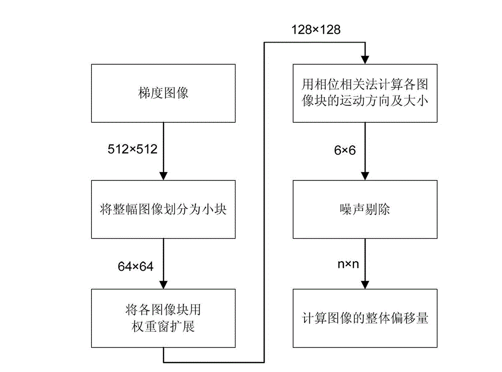
[0024] Step 1: Use a scanning probe microscope to obtain the height image of the sample surface at a fixed sampling interval. After each image is obtained, the height of each pixel is subtracted from the height of the adjacent pixel to obtain a gradient image of the sample surface , to eliminate the effect of z-drift.

[0025] Specifically, the relationship between the height images of the sample surface acquired at adjacent sampling moments can be written as h k+1 (x,y)=h k (x+Δx k ,y+Δy k )+Δz k , where h k (x, y) is the height value of the sample surface height image at point (x, y) acquired at the sampling time k, Δx k , Δy k , Δz k Represents the drift of the sample in the three directions of x, y, and z from the time of sampling k to the time of sampling k+1. Now introduce the gradient g k (x,y)=h k ...


PUM


Abstract

The invention discloses a method of temperature drift estimating and compensating in a scanning probe microscope, the method includes using the scanning probe microscope to obtain sample surface images at fixed sampling intervals, dividing each image into a plurality of pieces to carry out gradient processing, using a phase correlation method to calculate the drift distances of the images obtained at adjacent sampling times in the X and Y directions, using the density cluster density-based spatial clustering of applications with noise (DBSCAN) algorithm to reject noisy data and then calculating the whole drift distances of the images; then using the neural network method to speculate the drift distance at a next sampling time according to the previous drift distances and present near-field temperature data, and furthermore improving neural network parameters according to drift distance data obtained by actual measurement and calculation; and speculating obtained drift distance at the next sampling time and inputting the drift distance to a controller as a feed-forward signal, wherein compensation is made by the controller according to the feed-forward signal, so that the temperature drift is restrained, and automatic control is achieved. The temperature drift generated by the scanning probe microscope along with time in the environment without strict temperature and humidity control can be effectively restrained.

Description

technical field [0001] The invention relates to a method for estimating and compensating the temperature drift during the working process of a scanning probe microscope in an environment without strict temperature and humidity environment control. Background technique [0002] Currently, research using scanning probe microscopy involves more and more fields. It is not only used to obtain the surface morphology of objects, but also to manipulate particles at the nanoscale. For example, researchers have been studying the operation of using an atomic force microscope (AFM) to push particles with a diameter of 10nm. However, there are still many problems to be solved in order to realize the automatic production of nanoscale objects. Because when using AFM to operate particles without strict temperature and humidity environmental control, there are many uncertainties that require the operator to make manual intervention compensation, such as the inherent scanning hysteresis of ...

Claims


Application Information

Patent Timeline
IPC IPC(8): G01Q30/00
Inventor 杨秦敏赵声卢建刚张杰孙优贤
Owner ZHEJIANG UNIV
Why Eureka
Try Eureka