
Optical mutual inductor calibration and operation monitoring method and system

An optical transformer and operation monitoring technology, which is applied in the direction of instruments, measuring electricity, and measuring devices, can solve problems such as power outages in substations and inconvenient measurements, and achieve accurate real-time monitoring, fast speed, and high efficiency.

Active Publication Date: 2013-04-24
STATE GRID CORP OF CHINA +1
View PDF7 Cites 6 Cited by
  • Summary
  • Abstract
  • Description
  • Claims
  • Application Information

AI Technical Summary

Problems solved by technology

The current optical transformer calibration technology requires on-site power off and on in the substation, which brings great inconvenience to the measurement.

Method used


Image

  • Optical mutual inductor calibration and operation monitoring method and system
  • Optical mutual inductor calibration and operation monitoring method and system
  • Optical mutual inductor calibration and operation monitoring method and system

Examples


Embodiment Construction

[0026] The present invention will be further explained below in conjunction with the drawings.

[0027] Such as figure 1 As shown, the optical transformer calibration and operation monitoring system of the present invention includes: a computer 1, a calibration unit 5, a merging unit 6, a CT electrical unit 7, a FOCT optical cable 8, a GIS 9, and an equal ampere-turn optical fiber sensitive ring 10. The calibration unit 5 includes a calibration module 2, an online operation monitoring module 3, and a current generation module 4. The GIS9 is a gas-insulated combined electrical equipment, which is used to install an equal ampere-turn optical fiber sensitive ring 10.

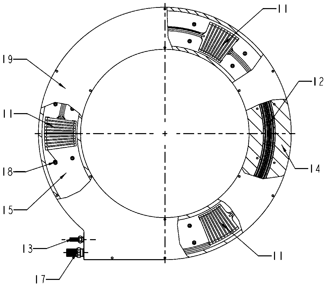
[0028] Such as figure 2 , 3 As shown, the equal-ampere-turn optical fiber sensitive ring 10 includes an equal-ampere-turn cable 11, an optical fiber 12, an optical fiber outlet 13, a sensitive ring body 14, a liner 15, a sealing ring 16, a cable inlet 17, and Cable blind section grounding screw 18, insulating cover 19...


PUM


Abstract

The invention provides an optical mutual inductor calibration and operation monitoring method and a system so as to solve the problem that measurement is inconvenient. The system comprises a computer, a calibration module, an on-line operation monitoring module, a current generation module, a combination unit, a computed tomography (CT) electrical unit, a fiber optical current transformer (FOCT) optical cable, a gas insulated switchgear (GIS), an equal ampere-turn cable and an equal ampere-turn optical fiber sensitive ring. The current generation module generates current signals. The equal ampere-turn cable amplifies the current signals penetrating through the equal ampere-turn sensitive ring. The calibration module collects the current signals inside the equal ampere-turn cable as the standard signals, receives detected current received by the CT electrical unit at the same time after framing of the combination unit, and transmits the detected current in a packaging mode to the on-line operation monitoring module. The on-line operation monitoring module processes received data, obtains ratio error value and angular difference value of a calibrated optical mutual inductor, and sends the ratio error value and the angular difference value to the computer. The method and the system monitor performance index of the optical mutual inductor on the condition that power is not off in real time, and are safe, high in calibration precision, fast in speed, and high in efficiency.

Description

Technical field [0001] The invention relates to a device measurement technology, more specifically to a transformer calibration and monitoring technology. Background technique [0002] Smart grid is one of the national strategic emerging industries. Transformers are important equipment for electric energy measurement and relay protection in the power system. Its long-term stability, reliability, and safety are closely related to the safe and stable operation of the power system. Traditional electromagnetic induction transformers are based on the principle of electromagnetic induction and have been applied for more than one hundred years. However, they have shortcomings such as flammability and explosion, and cannot meet the needs of the development of new power systems. [0003] Compared with traditional electromagnetic transformers, electronic voltage transformers have the advantages of high precision, high linearity, wide frequency band, small size and light weight. Electronic v...

Claims


Application Information

Patent Timeline
IPC IPC(8): G01R35/02G01R31/00
Inventor 李淮海张志鑫刘东伟张峰谭金权孙向东石梅荣崔锦瑞李洁何辉
Owner STATE GRID CORP OF CHINA
Learn More