Pulverizer

A grinding machine and frame technology, applied in grain processing, etc., can solve the problems of small impact acceleration of the grinding body, reduce the working efficiency of the grinding machine, and consume labor costs, so as to achieve fast feeding speed, reduce powder escape, The effect of improving work efficiency

Inactive Publication Date: 2013-05-01
JIANGSU PUGE MACHINERY
View PDF7 Cites 5 Cited by
  • Summary
  • Abstract
  • Description
  • Claims
  • Application Information

AI Technical Summary

Problems solved by technology

However, the transmission pulverizer only relies on the motor to drive a single grinding cylinder to rotate, which generally has the problems of long grinding time, small impact acceleration of the grinding body, and high energy consumption. In addition, it is necessary to manually take out the ground powder after stopping the machine, which consumes labor costs. At the same time, it also reduces the working efficiency of the pulverizer
In addition, the problem of dust has always been a persistent disease of the pulverizer

Method used


Image

  • Pulverizer

Examples


Embodiment Construction

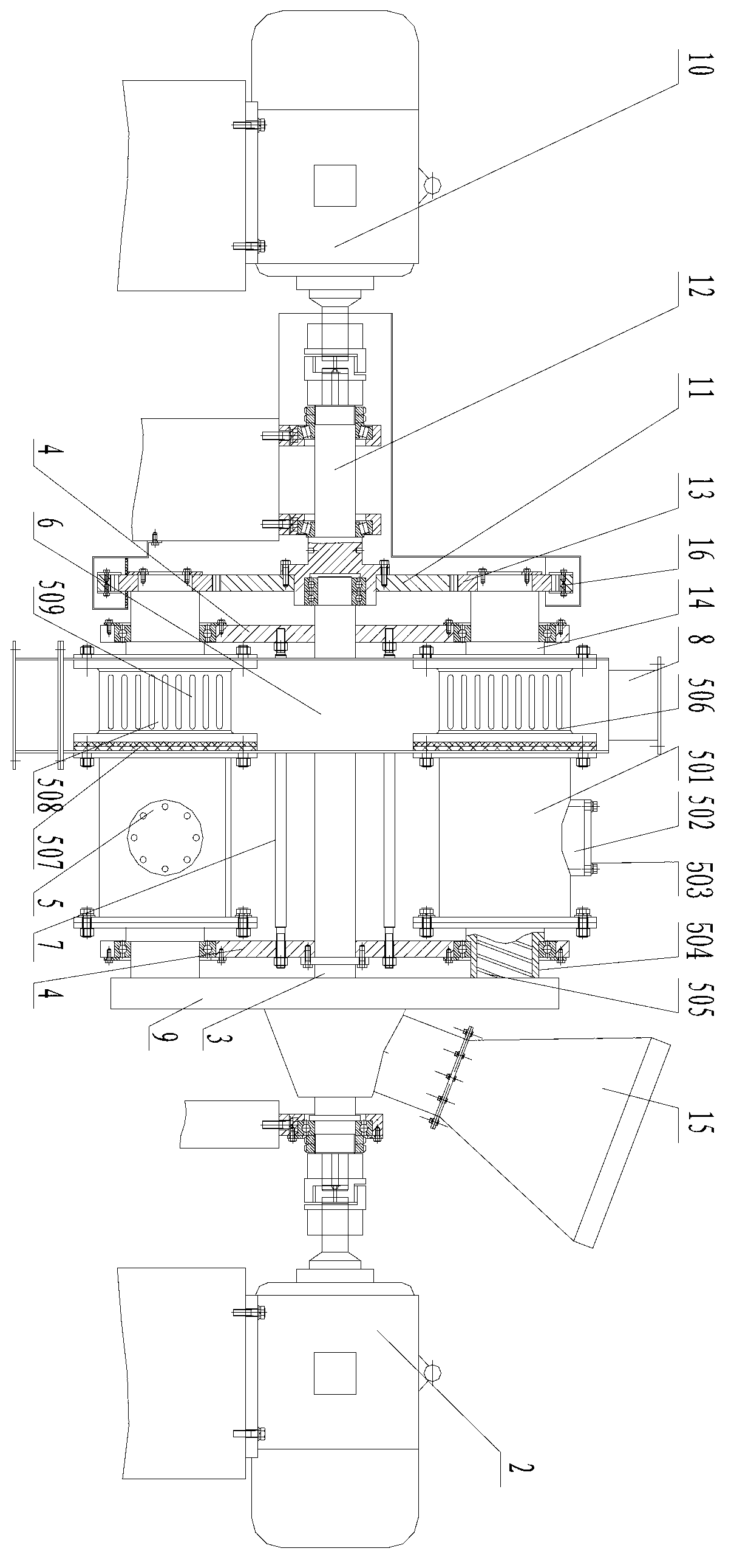
[0026] Specific embodiments of the present invention will be described in detail below in conjunction with the accompanying drawings.

[0027] Such as figure 1 As shown, a pulverizer comprises a frame 1, on which a main shaft 3 driven by a revolving power device 2 is movably arranged, and two revolving disks 4 are set on the main shaft 3, and two revolving disks 4 Three abrasive devices 5 are arranged between them and the abrasive devices 5 are evenly distributed in the circumferential direction. The abrasive device 5 includes a grinding cylinder body 501 provided with a grinding body inlet 502 and a cover plate 503. device, the other side of the barrel body 501 is provided with a discharge device 506 . The feeding device is a hollow shaft 504, and a screw conveying blade 505 is arranged inside the hollow shaft 504. One end of the hollow shaft 504 is connected with the grinding cylinder body 501, and the other end is passed through the revolving disk 4 through a bearing. The...


PUM


Abstract

The invention discloses a pulverizer which comprises a rack. The rack is movably provided with a spindle driven by a revolution power device; the spindle is sleeved with two revolution disks; a plurality of grinding devices are arranged between the two revolution disks and are peripherally and uniformly distributed; the spindle is sleeved with a material divider communicated with the feed ends of the grinding devices; the material divider is communicated with a feed hopper arranged on the rack; the rack is provided with a driving gear driven by a rotation power device; the discharge end of each grinding device is provided with a driven gear meshed with the driving gear; each grinding device comprises a grinding cylinder body; the side of each grinding cylinder body, which is close to the revolution power device, is provided with a feeding device; the end part of each feeding device is inserted in the corresponding revolution disk and is communicated with the material divider; the other side of each grinding cylinder body is provided with a discharge device; and the discharge devices on the grinding cylinder bodies on the spindle are sleeved with two discharge cover plates; and discharge bins are arranged outside the discharge cover plates on the rack. The invention provides the pulverizer with high working efficiency and low energy consumption.

Description

technical field [0001] The invention relates to a pulverizer. Background technique [0002] The grinding machine is to put the grinding body (usually steel ball, steel section) into the grinding cylinder body, rely on the rotation of the grinding cylinder body to drive the grinding body to repeatedly hit the material to be ground, and use the impact acceleration of the grinding body to increase the impact stress on the material so that Equipment that crushes materials and finally grinds them into powder. However, the transmission pulverizer only relies on the motor to drive a single grinding cylinder to rotate, which generally has the problems of long grinding time, small impact acceleration of the grinding body, and high energy consumption. In addition, it is necessary to manually take out the ground powder after stopping the machine, which consumes labor costs. Also reduced the working efficiency of pulverizer simultaneously. In addition, the problem of dust has always b...

Claims


Application Information

Patent Timeline
Patent Type & Authority Applications(China)
IPC IPC(8): B02C17/10B02C17/24B02C17/18
Inventor 钱海燕吕镇江张祖洪高兴坤
Owner JIANGSU PUGE MACHINERY
Why Eureka
Try Eureka