Preparation method of LED radiating fin with large radiating area

A technology of heat dissipation fins and heat dissipation area, applied in lighting and heating equipment, semiconductor devices of light-emitting elements, cooling/heating devices of lighting devices, etc., can solve the problems of low corrosion resistance, increased volume and weight, etc.

Active Publication Date: 2020-08-07
哈尔滨鑫科纳米科技发展有限公司
View PDF4 Cites 0 Cited by
  • Summary
  • Abstract
  • Description
  • Claims
  • Application Information

AI Technical Summary

Problems solved by technology

[0009] In order to solve the existing problems of increasing the heat dissipation area of ​​LED heat dissipation fins, which often bring about increased volume and weight, and the low corrosion resistance of the currently used large-area AI-Mg alloy heat dissipation fins, the present invention provides a The preparation method of the new large heat dissipation area LED heat dissipation fin comprises the following steps:

Method used


Image

  • Preparation method of LED radiating fin with large radiating area
  • Preparation method of LED radiating fin with large radiating area
  • Preparation method of LED radiating fin with large radiating area

Examples


preparation example 1

[0072] Preparation Example 1 Preparation of titanium nano polymer colloid:

[0073] 100g of pure titanium powder with metal content greater than 99.5%, pulverizer (low molecular weight epoxy resin E51) with 5% wt of titanium powder, pulverizer (oleic acid) with 5% wt of titanium powder, and 0.5% dispersant (byk170) was added to 100g colloidal carrier (xylene) together, stirred at 300rpm and mixed uniformly, took the mixture and added it to the pulverizer's tank for 3h grinding, after grinding, it was naturally cooled to room temperature, and then filtered to obtain the fineness Titanium nano-preliminary polymer below 50-75nm; then, 0.1%wt of anti-flocculant (naphthalene sulfonate formaldehyde condensate) and 0.2% wt of anti-flocculant of titanium powder mass are added to the titanium nano-prepolymer. Precipitating agent (stearic acid) and anti-precipitation agent (BYK410) with 2.5% titanium powder mass were colloidized by a horizontal ball mill for 2 hours, and finally a titanium...

preparation example 2

[0084] Preparation Example 2 Preparation of graphene colloid:

[0085] The composition of graphene colloid (in parts by mass) is: 5 parts of graphene, 0.1 part of wetting and dispersing agent, 10 parts of crosslinking agent, 0.3 part of anti-flocculant, 0.5 part of anti-settling agent, and 100 parts of colloidal carrier; Graphene 5 parts, wetting and dispersing agent (wetting and dispersing agent S596) 0.1 parts, crosslinking agent (2,5-dimethyl-2,5 di-tert-butylperoxyhexane) 10 parts, colloidal carrier (ring 100 parts of oxygen resin F51), stirred and mixed at 300 rpm, put into the tank of special equipment for graphene polymer preparation (disclosed in patent CN201821944605.6), grind for 2 hours to obtain the graphene colloid primary polymer; 0.3 part of anti-flocculant (Efka LP-9009) and 0.5 part of anti-settling agent (Deqian 202P) were added to the polymer, and the graphene colloid was obtained by grinding with a high-energy grinder for 1 hour.

preparation example 3

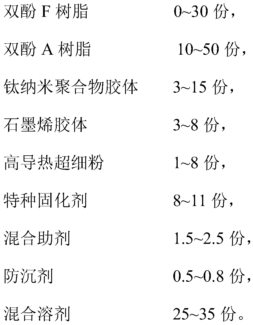
[0086] Preparation Example 3 Preparation of a rare metal heat-dissipating anti-corrosion coating for LED radiating fins: According to the following formula (in parts by mass):

[0087]

[0088] (1) Component A: add 33 parts of the above two resins, titanium nano polymer colloid, graphene colloid, silicon carbide, BYK301, BYK410 and mixed solvent into the paint tank, start stirring, mix evenly; sand to fine Degree 30μm, packed in bucket;

[0089] (2) Part B: Take T31 and add 12 parts of mixed solvent, and stir evenly.


PUM

PropertyMeasurementUnit
particle diameteraaaaaaaaaa
thicknessaaaaaaaaaa
thicknessaaaaaaaaaa

Abstract

The invention provides a preparation method of an LED radiating fin with a large radiating area, aiming at solving the problems that an existing method for increasing a radiating area of an LED radiating fin often causes volume and weight increase and the like. The method comprises the following steps: deburring, chemically degreasing, washing, drying and locally sealing the LED radiating fin; andcarrying out electrochemical treatment on the treated LED radiating fin in an electrolyte. According to the LED radiating fin prepared by the method, on the premise that the weight of the fin is notincreased, the radiating area is increased by more than 5 times compared with an original area, and the radiating effect is effectively improved.

Description

Technical field [0001] The invention relates to LED lamp heat dissipation technology, in particular to a method for preparing LED heat dissipation fins with a large heat dissipation area. [0002] It mainly involves the enlargement and protection of the heat dissipation area of ​​the LED lamp radiating fins to improve its heat dissipation capacity, and at the same time endow the new heat dissipation surface with anti-corrosion and anti-fouling functions, and maintain its heat dissipation performance for a long time without attenuation, thereby extending the life of the LED. Background technique [0003] As a modern advanced energy-saving light source, LED lights are developing rapidly and are a major scientific and technological project in my country. The lifetime of an LED lamp is determined by its junction temperature. For example, the lifetime of a high-power white LED's junction temperature when the brightness is attenuated by 70% is as follows: [0004] Junction temperature...

Claims


Application Information

Patent Timeline
Patent Type & Authority Applications(China)
IPC IPC(8): F21V29/503F21V29/74C09D163/00C09D5/10C09D7/61C09D7/63F21Y115/10
CPCF21V29/503F21V29/74C09D163/00C09D5/10C09D7/61C09D7/63F21Y2115/10C08K2003/385C08L2205/025C08L63/00C08K13/02C08K3/08C08K3/042C08K5/14C08K5/09C08K3/34C08K3/38
Inventor 薛俊峰朱兰芬
Owner 哈尔滨鑫科纳米科技发展有限公司
Why Eureka
Try Eureka