Torsional impact drilling acceleration tool
A technology of percussion drilling and tools, which is applied in drilling equipment, driving devices for drilling in boreholes, earthwork drilling and production, etc. It can solve problems such as stuck pipe, low safety, and affecting the quality of the wellbore, so as to avoid failure and improve use The effect of longevity
- Summary
- Abstract
- Description
- Claims
- Application Information
AI Technical Summary
Problems solved by technology
Method used
Image

Examples
Embodiment Construction
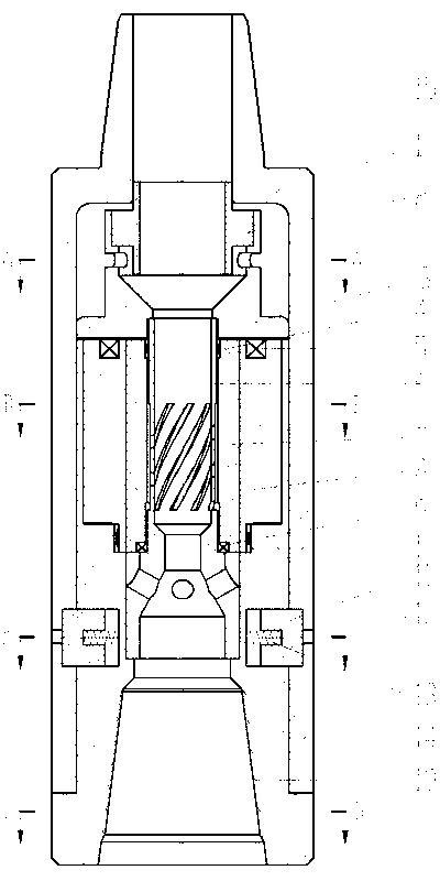
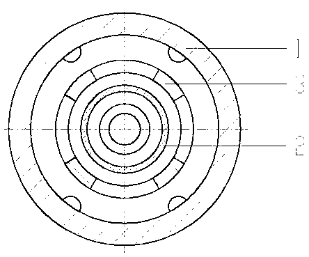
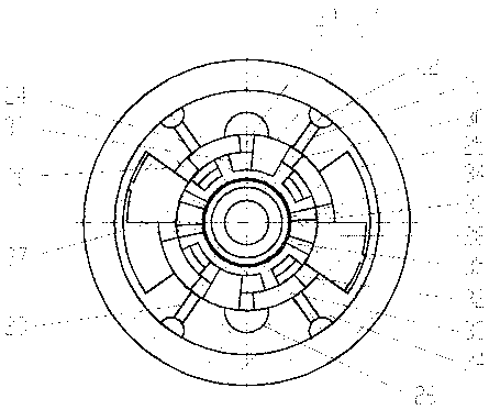
[0028] Such as figure 1 As shown, a torsional percussion drilling speed-increasing tool of the present invention includes a housing 1, a seat body 14, a flow guide unit, an impact unit and an anti-dropping unit; Buckle 15, the lower end is provided with the housing spline 16 that cooperates with the seat body spline 20, and the interior of the housing 1 includes a flow guide unit, an impact unit and an anti-drop unit; the upper end of the seat body 14 is provided with a The inner cavity, the lower end is provided with a female button 19 for connecting the drill bit and a seat body spline 20 for interacting with the shell spline 16; the flow guide unit includes a sand removal sleeve 2, a sealing cover 3 and a screen pipe 6; The impact unit includes a positioning sleeve 7, an impact hammer 8, an upper needle bearing 4, an upper deep groove ball bearing 5, a lower deep groove ball bearing 9 and a lower needle bearing 10, and the impact hammer 8 is provided with a starting hammer ...
PUM
 Abstract
Description
Claims
Application Information
 - R&D
- Intellectual Property
- Life Sciences
- Materials
- Tech Scout
- Unparalleled Data Quality
- Higher Quality Content
- 60% Fewer Hallucinations
Browse by: Latest US Patents, China's latest patents, Technical Efficacy Thesaurus, Application Domain, Technology Topic, Popular Technical Reports.
© 2025 PatSnap. All rights reserved.Legal|Privacy policy|Modern Slavery Act Transparency Statement|Sitemap|About US| Contact US: help@patsnap.com