AI technical title is built by Patsnap AI team. It summarizes the technical point description of the patent document.
A steel reinforced concrete and steel plate technology, which is applied to shaft equipment, earthmoving, wellbore lining, etc., can solve the problems of limited increase in steel content inside the shaft wall and insignificant contribution to the horizontal bearing capacity of the shaft wall, etc., so as to reduce engineering costs. , Wide applicability, high steel content
Active Publication Date: 2014-10-29
CHINA UNIV OF MINING & TECH
View PDF5 Cites 0 Cited by
Summary
Abstract
Description
Claims
Application Information
AI Technical Summary
This helps you quickly interpret patents by identifying the three key elements:
Problems solved by technology
Method used
Benefits of technology
Problems solved by technology
However, the most unfavorable part of the well wall is the inner area. This type of well wall uses double-layer steel plates to implement overall radial restraint on the well wall. limited; on the other hand, the increase in the strength of the external concrete does not contribute significantly to the horizontal bearing capacity of the shaft wall
Method used
Image
Click on the blue label to locate the original text in one second.
Reading with bidirectional positioning of images and text.
Examples
Embodiment 1
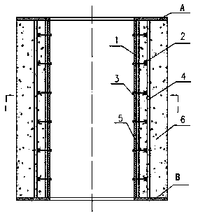
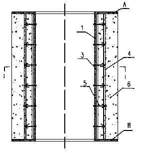
[0042] Example 1: Drilling method shaft wall (prefabricated in sections, with annular flange plates at both ends of the shaft wall)
[0043] The steel plate steel-reinforced concrete shaft wall created by the present invention is mainly composed of steel plate cylinder 1, circumferential steel frame 2 (H-shaped steel), inner vertical steel frame 3 (H-shaped steel), outer vertical steel frame 4 (H-shaped steel), diameter Composed of connecting piece 5 and concrete 6 (see Picture 1-1 with Figure 1-2 ).
Embodiment approach
[0045] (1) On the flange plate at the lower end of the shaft wall, arrange the outer vertical steel frame 4 and the inner vertical steel frame 3 along different ring diameters (the ring spacing and circumferential spacing can be adjusted as required) and welded to the flange plate;
[0046] (2) Install and fix the section steel arc section to the outer vertical steel frame 4, and form a closed circumferential steel frame 2 by welding or bolt connection; then install and fix the pre-bent formed curved steel plate to the inner vertical steel frame 3. , The closed steel plate cylinder 1 is formed by welding;
[0047] (3) Utilize the radial coupling 5 to connect the steel plate cylinder 1 and the circumferential steel frame 2 to form a space structure;
[0048] (4) Install the upper flange plate and weld it firmly to the inner vertical steel frame, the outer vertical steel frame, and the steel plate cylinder;
[0049] (5) Install the external formwork and supporting structure required for...
Embodiment 2
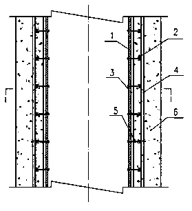
[0051] Example 2: Drilling method shaft wall (prefabricated in sections, with annular flange plates at both ends of the shaft wall)
[0052] The steel plate steel-reinforced concrete shaft wall created by the present invention is mainly composed of steel plate cylinder 1, circumferential steel frame 2 (channel steel), inner vertical steel frame 3 (channel steel), outer vertical steel frame 4 (channel steel), diameter Composed of connecting piece 5 and concrete 6 (see diagram 2-1 with Figure 2-2 ).
[0053] Implementation method: same as the first embodiment.
PUM
Abstract
The invention discloses a steel plate and steel reinforced concrete well wall, which is mostly suitable for deep vertical shafts for bearing high ground pressure and high water pressure. A steel plate cylinder, an annular steel rib, inside vertical steel ribs, outside vertical steel ribs and radial connecting pieces are arranged and concrete is poured to form a cylindrical well wall. The steel plate cylinder and the annular steel rib are respectively positioned on the inner surface of the well wall and in the well wall, and are respectively fixed to the inside and outside vertical steel ribs; the steel plate cylinder and the annular steel rib are connected through the radial connecting pieces to form a spatial structure; and concrete is poured into an annular space formed by the steel plate cylinder and a well wall template or surrounding rock to coat the annular steel rib, the inside and outside vertical steel ribs and the like, and the cylindrical well wall structure is formed. The steel ratio on the inner side of the well wall is high, the concrete between the steel plate cylinder and the annular steel rib is positioned in a three-directional stress state, the compressive strength can be obviously improved, a core bearing area is formed, and the ultimate bearing capacity of the well wall is greatly improved. The steel plate and steel reinforced concrete well wall is used for building deep vertical shafts, the thickness of the well wall can be greatly reduced and the cost is reduced; and the steel plate and steel reinforced concrete well wall is reasonable in structure and easy and convenient to construct and has wide applicability.
Description
1. Technical Field [0001] The invention relates to a steel plate steel-reinforced concrete shaft wall, which is especially suitable for deep shaft shafts in deep alluvium and water-rich rock formations for mine construction, such as ordinary sinking, freezing, drilling and caisson shafts. 2. Background technology [0002] With the development of deep mineral resources in our country, the depth of shaft construction continues to increase, and the bearing capacity of the shaft wall has to be greatly increased to withstand increasing deep ground pressure. To this end, there are only two ways: one is to keep the structure of the shaft wall unchanged to increase its material strength and thickness; the other is to change the structure of the shaft wall. At present, the commonly used reinforced concrete wall structure has been difficult to meet the needs of deep mine construction, and the cast iron or cast steel shaft wall, Qiubin block shaft wall, concrete arc slab shaft wall used in ...
Claims
Application Information
Patent Timeline
Application Date:The date an application was filed.
Publication Date:The date a patent or application was officially published.
First Publication Date:The earliest publication date of a patent with the same application number.
Issue Date:Publication date of the patent grant document.
PCT Entry Date:The Entry date of PCT National Phase.
Estimated Expiry Date:The statutory expiry date of a patent right according to the Patent Law, and it is the longest term of protection that the patent right can achieve without the termination of the patent right due to other reasons(Term extension factor has been taken into account ).
Invalid Date:Actual expiry date is based on effective date or publication date of legal transaction data of invalid patent.

