
Coal retaining structure of mine conveyor

A technology of loader and mine, which is used in earth-moving drilling, transportation and packaging, underground transportation, etc., to achieve the effect of light and fast bolt connection, simple structure and convenient use.

Inactive Publication Date: 2013-05-01
SHAANXI HUABIN COAL IND
View PDF0 Cites 0 Cited by
  • Summary
  • Abstract
  • Description
  • Claims
  • Application Information

AI Technical Summary

Problems solved by technology

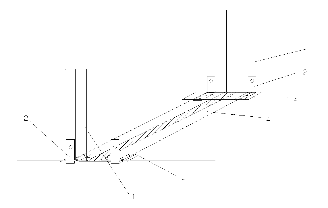
[0003] The purpose of the present invention is to provide a coal retaining structure for a mine reloader in order to solve the need to manually clean up coal leakage when the reloader moves forward, improve equipment defects, and reduce the labor force of workers

Method used


Image

  • Coal retaining structure of mine conveyor

Examples


Embodiment Construction

[0008] The present invention will be described in detail below in conjunction with the accompanying drawings and specific embodiments.

[0009] see figure 1 , the present invention arranges base plate 4 on the chute bottom plate of transfer machine 1, the two sides of base plate 4 are respectively connected with hoop 2 by bolts, the other side of two hoops 2 is connected with transfer machine 1 by bolts, two hoops Lining plates 3 are respectively arranged between 2 and the base plate 4 .

[0010] Use process: stick the bottom plate 4 to the bottom plate of the chute of the transfer machine 1, press the liner 3 tightly on the bottom plate 2, press the liner 3 through the hoop 2, connect the transfer machine 1 and the hoop 2 with the bolt 5, pass The hoop 2 and the bolts press the liner 3 onto the bottom plate 4, so that the bottom plate 4 is close to the bottom plate of the chute of the transfer machine 1. After assembly, the bolts are connected and fastened, so that the coal ...


PUM


Abstract

The invention relates to a coal retaining structure of a mine conveyor. An SZZ900 conveyor is adopted on a transport gate road of an ZF4404 working surface, a gap with a width of 300 to 400mm is formed on the connected part of a concave groove of an overhead section of the conveyor and an upslope inclined groove due to design defects, the fine coal dust continuously leaks from the gap and is gradually accumulated when the conveyor runs, and then the conveyor is affected to move forwards. The special cleaning of leaked coal needs to be carried out when the conveyor is moved forwards during each shift, and then the conveyor can be moved forwards, so the production time is affected, and the labor strength of workers is increased. A chute bottom plate of the conveyor is provided with a bottom plate, both sides of the bottom plate are respectively connected with a coupling by a bolt, the other sides of the two couplings are connected with the conveyor by bolts, and lining plates are respectively arranged between the two couplings and the bottom plate. The coal retaining structure has the advantages that the structure is simple, the convenience in use is realized, and the bolt connection is easy, convenient and rapid.

Description

technical field [0001] The invention relates to a coal retaining structure for a mine transfer machine. Background technique [0002] The ZF4404 working face is transported along the chute using the SZZ900 transfer machine. Due to design defects, there is a gap of 300-400mm wide at the junction of the empty section of the transfer frame and the uphill chute. During the operation of the transfer machine, fine coal is constantly Leakage from the gaps will accumulate more and more, affecting the forward movement of the transfer machine. In each shift, the coal leakage must be cleaned before the transfer machine can be moved forward, which not only affects the production time, but also increases the labor force of workers. Contents of the invention [0003] The purpose of the present invention is to provide a coal retaining structure for a mine reloader in order to solve the problem of manual cleaning of coal leakage when the reloader is moving forward, improve equipment defec...

Claims


Application Information

Patent Timeline
Patent Type & Authority Applications(China)
IPC IPC(8): E21F13/06
Inventor 连旭东周贤
Owner SHAANXI HUABIN COAL IND
Learn More