Quick inflator

A pumping pump, fast technology, applied in the direction of liquid variable volume machinery, variable volume pump components, machines/engines, etc., can solve the problems of small displacement, low work efficiency, slow pumping speed, etc. The effect of large, high work efficiency and fast boosting speed

Inactive Publication Date: 2013-05-01
NANTONG GUANGXING PNEUMATIC EQUIP
View PDF9 Cites 10 Cited by
  • Summary
  • Abstract
  • Description
  • Claims
  • Application Information

AI Technical Summary

Problems solved by technology

[0002] At present, the piston of ordinary pumps travels up and down, and can only be compressed and pumped once in the next stroke. The displacement is small, the pumping speed is slow, and the working efficiency is very low.

Method used


Image

  • Quick inflator
  • Quick inflator

Examples


Embodiment Construction

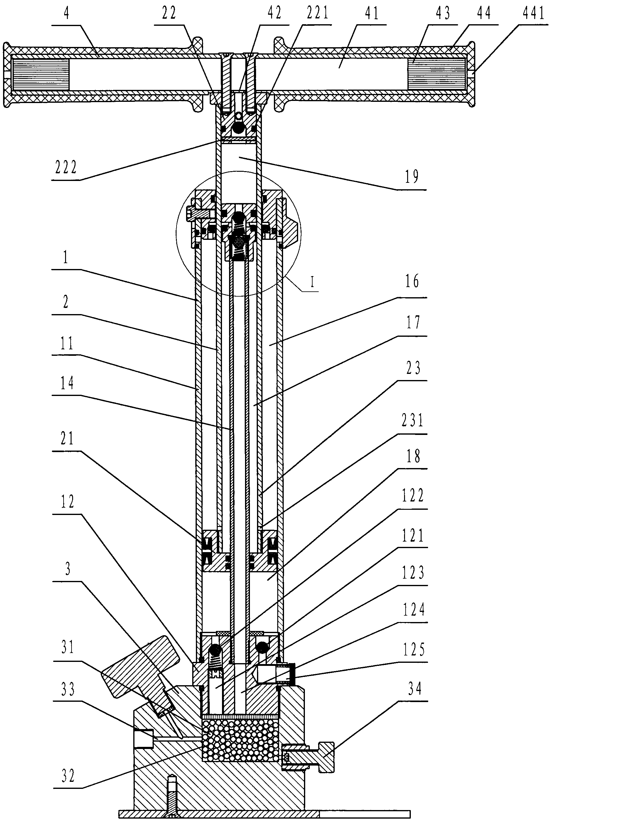
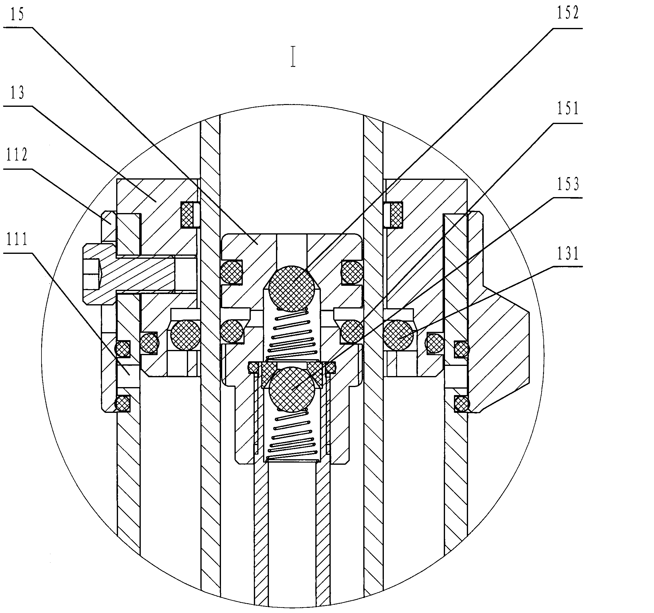
[0016] Such as figure 1 and figure 2 Shown: a quick pump, which is composed of a pump 1, a piston 2, a base 3 and a handle 4. The gas cylinder 1 is composed of a cylinder body 11 , a cylinder bottom 12 , a cylinder cover 13 , an air guide tube 14 and a valve seat 15 . The air guide tube 14 is located at the center of the cylinder body 11, the lower end is fixed on the cylinder bottom 12, and the upper end is connected with a fixed valve seat 15; the piston 2 is composed of a piston one 21, a piston two 22 and a hollow piston rod 23 with a through hole 231 at the lower end. composition. The hollow piston rod 23 is located outside the air duct 14 and the valve seat 15, the lower end is connected with the fixed piston 1 21, and the upper end is connected with the fixed piston 2 22; The outer wall forms the air chamber 2 17, the piston 1 21 and the cylinder bottom 12 form the air chamber 3 18, the piston 22 and the valve seat 15 form the air chamber 4 19; the base 3 and the lo...


PUM


Abstract

The invention discloses a quick inflator, which consists of an inflator, a piston, a base and a handle, wherein the inflator consists of an inflator body, an inflator bottom, an inflator cover, an air guide pipe and a valve seat, wherein the air guide pipe is arranged in the center of the inflator body, the lower end of the air guide pipe is fixed to the inflator bottom, and the upper end of the air guide pipe is fixedly connected to the valve seat; the piston consists of a piston I, a piston II and a hollow piston rod; the hollow piston rod is arranged outside the air guide pipe and the valve seat, the lower end of the hollow piston rod is fixedly connected to the piston I, and the upper end of the hollow piston rod is fixedly connected to the piston II; the outer wall of the hollow piston rod and the inner wall of the inflator body form an air cavity I, and the inner wall of the hollow piston rod and the outer wall of the air guide pipe form an air cavity II; the piston I and the inflator bottom form an air cavity III; and the piston II and the valve seat form an air cavity IV. The quick inflator has the greatest advantages that the piston I and the piston II move vertically to compress and discharge air in each travel, the air displacement is high, the rate of pressure rise is high, and the work efficiency is high, and is three to four times that of the common inflator at present.

Description

technical field [0001] The invention relates to a quick air pump, in particular to a quick air pump with a piston capable of compressing and pumping air in an up and down stroke. Background technique [0002] At present, the up and down strokes of the common inflator piston can only be compressed and inflated once in the next stroke. The displacement is small, the inflating speed is slow, and the work efficiency is very low. Contents of the invention [0003] In order to solve the above-mentioned disadvantages existing in the current common pump, the present invention provides a quick pump, which is composed of a pump, a piston, a base and a handle. It is characterized in that: the gas cylinder is composed of a cylinder body, a cylinder bottom, a cylinder cover, an air guide pipe and a valve seat. The air guide tube is arranged in the center of the barrel, the lower end is fixed on the bottom of the barrel, and the upper end is connected to a fixed valve seat; the piston ...

Claims


Application Information

Patent Timeline
IPC IPC(8): F04B33/00F04B39/12F04B39/10F04B39/00
Inventor 高雪峰
Owner NANTONG GUANGXING PNEUMATIC EQUIP
Why Eureka
Try Eureka