
Gas spring with plurality of spiral columns

A gas spring and helical column technology, which is applied in the field of spring manufacturing, can solve problems such as complex structure, impact on health, and high requirements for parts matching, and achieve good horizontal and vertical ventilation, eliminate the impact on human health, and overcome the effect of complex structure

Active Publication Date: 2013-05-01
XILINMEN FURNITURE
View PDF9 Cites 3 Cited by
  • Summary
  • Abstract
  • Description
  • Claims
  • Application Information

AI Technical Summary

Problems solved by technology

The elastic force of this type of compression spring is not adjustable after it is formed, and it still occupies a large space after being compressed. After being used in places such as spring mattresses, it cannot guarantee that each area of ​​use will have a satisfactory degree of comfort.
Although someone has designed a gas spring, it is composed of a cylinder, a piston (push rod), an additional built-in spring, etc., and has a complex structure and high requirements for cooperation between parts. A cavity is formed in the middle to achieve the spring effect, but it has the disadvantage of not being ventilated up and down. When it is used as a mattress compression spring, the moisture generated by the human body or in the environment will accumulate and cannot be removed through air convection. The human body is in the air full of moisture. Sleeping on a spring mattress will inevitably affect your health; in addition, the above-mentioned gas spring has insufficient deformation stroke, the softness adjustment range is small, and the non-use state still occupies a large space

Method used


Image

  • Gas spring with plurality of spiral columns
  • Gas spring with plurality of spiral columns
  • Gas spring with plurality of spiral columns

Examples


Embodiment 1

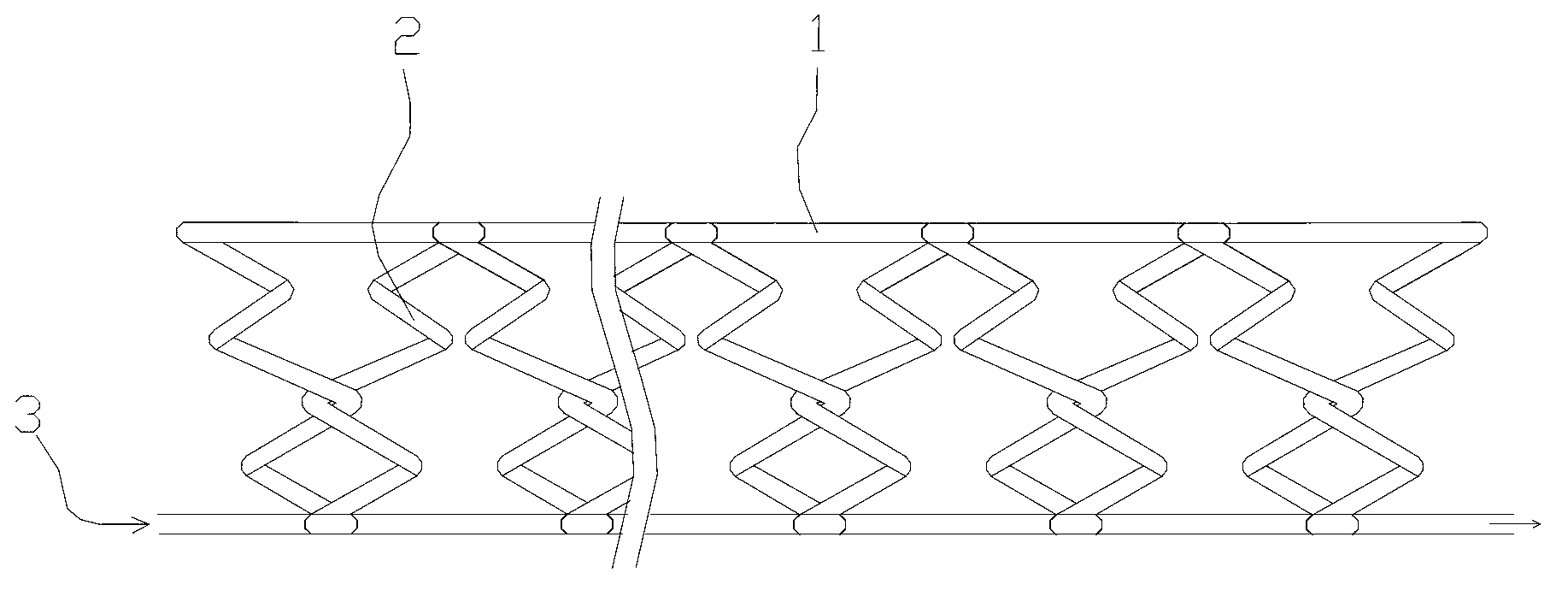
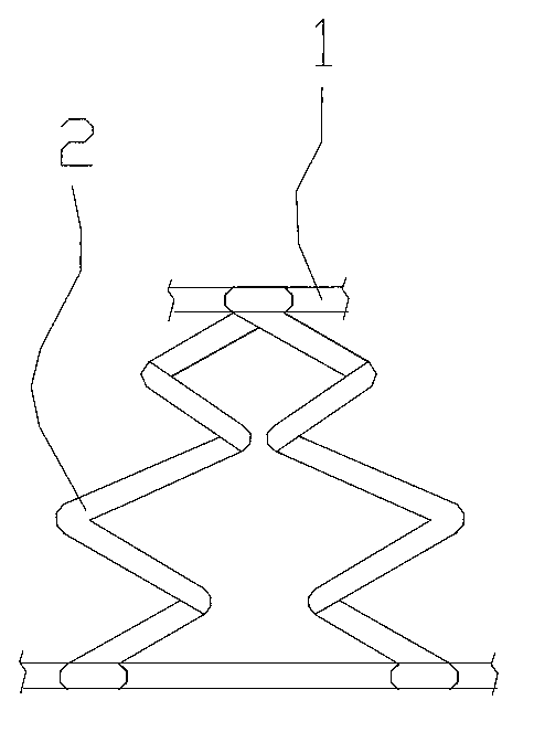
[0022] Such as Figure 1-Figure 4 As shown, a gas spring with a plurality of helical columns described in this embodiment includes a spring body, and the spring body is composed of a bar-shaped gas column 1 with a pressure gas containing chamber, and the gas column 1 A plurality of side-by-side and inclined spiral columns 2 are formed through repeated alternating spirals from top to bottom or bottom to top. The two adjacent spiral columns 2 form a figure-eight spiral unit, and the adjacent spiral units are connected with each other. , the air column 1 is provided with at least one vent hole 3 communicating with the containing chamber, and two vent holes 3 can be provided at both ends of the air column 1, one for inflation and one for exhaust.

[0023] The two adjacent helical columns 2 are arranged symmetrically, the inclination directions of the two separated helical columns 2 are consistent, and the heights of each helical column 2 are consistent, which is convenient for for...


PUM


Abstract

The invention discloses a gas spring with a plurality of spiral columns, wherein a technical problem that conventional gas springs are complicated in structure and airproof up and down is solved. The gas spring comprises a spring body, and is characterized in that the spring body is formed by a bar-like air column which is provided with a pressure gas containing cavity; the air column repeatedly and alternately spirals from top to bottom or from bottom to top and forms the plurality of side-by-side and inclined spiral columns; the two adjacent spiral columns form a splay spiral unit; the adjacent spiral units are mutually connected; and at least one air hole for communicating the containing cavity is formed in the air column. According to the gas spring disclosed by the invention, the spiral columns are formed by one gas column, the interconnectedness is good, when the gas spring is subject to pressure, the spiral columns are mutually squeezed to buffer the pressure, the gas pressure is uniformly adjusted more conveniently, and the ventilation is good. Moisture of a mattress formed by the gas springs is easy to remove, hardness is convenient to adjust and the mattress is large in unidirectional deformation range; various requirements are met; the mattress also can be adjusted in real time; and the comfort level of the mattresses is increased.

Description

technical field [0001] The invention relates to the technical field of spring manufacturing, in particular to an air pressure spring with a plurality of helical columns. Background technique [0002] "Spring" can be divided into compression spring, torsion spring and tension spring in terms of function. The commonly used compression spring is made of steel wire and other elastic metal wires in a spiral shape, and its elastic deformation is used to generate elastic force. The elastic force of this type of compression spring is not adjustable after it is formed, and it still occupies a large space after being compressed. After being used in places such as spring mattresses, it cannot guarantee that each area of ​​use has a satisfactory degree of comfort. Although someone has designed a gas spring, it is composed of a cylinder, a piston (push rod), an additional built-in spring, etc., and has a complex structure and high requirements for cooperation between parts, especially th...

Claims


Application Information

Patent Timeline
IPC IPC(8): F16F9/04F16F9/32F16F9/54A47C27/08A47C27/10
Inventor 陈阿裕
Owner XILINMEN FURNITURE
Learn More