Air spring

A technology of air springs and hollow parts, applied in the direction of gas shock absorbers, etc., can solve the problems of hindering the smooth displacement of the metal parts of the stopper parts, and it is difficult to ensure the cushioning performance, and achieve the effect of improving the cushioning performance and smooth displacement.

Active Publication Date: 2013-05-01
SUMITOMO ELECTRIC IND LTD
View PDF14 Cites 14 Cited by
  • Summary
  • Abstract
  • Description
  • Claims
  • Application Information

AI Technical Summary

Problems solved by technology

In this case, the stopper metal piece receives frictional resistance due to contact with other structural members, and due to the influence of this frictional resistance, smooth displacement of the stopper metal piece in the main load direction may be hindered
Therefore, the spring constant (elasticity) of the stopper member arranged in contact with the lower part of the stopper member metal fitting cannot be fully exerted, and as a result, there is a problem that it is difficult to ensure good cushioning performance in the deflated state.

Method used


Image

  • Air spring
  • Air spring
  • Air spring

Examples


Embodiment approach 1

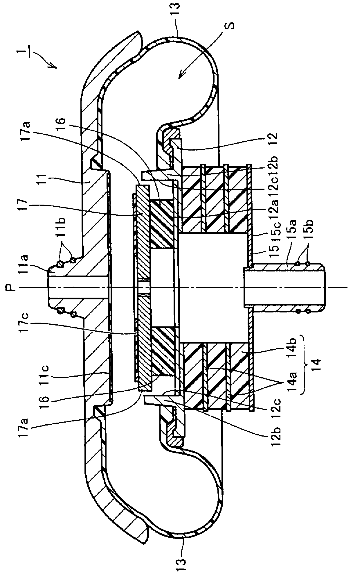
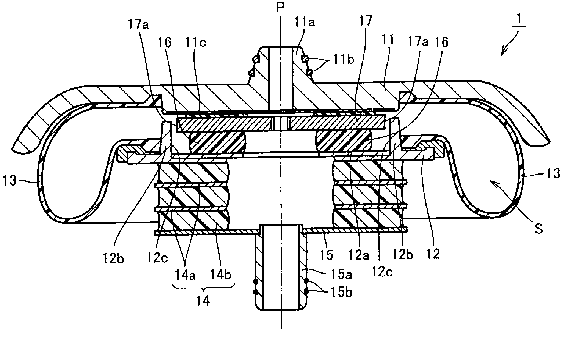
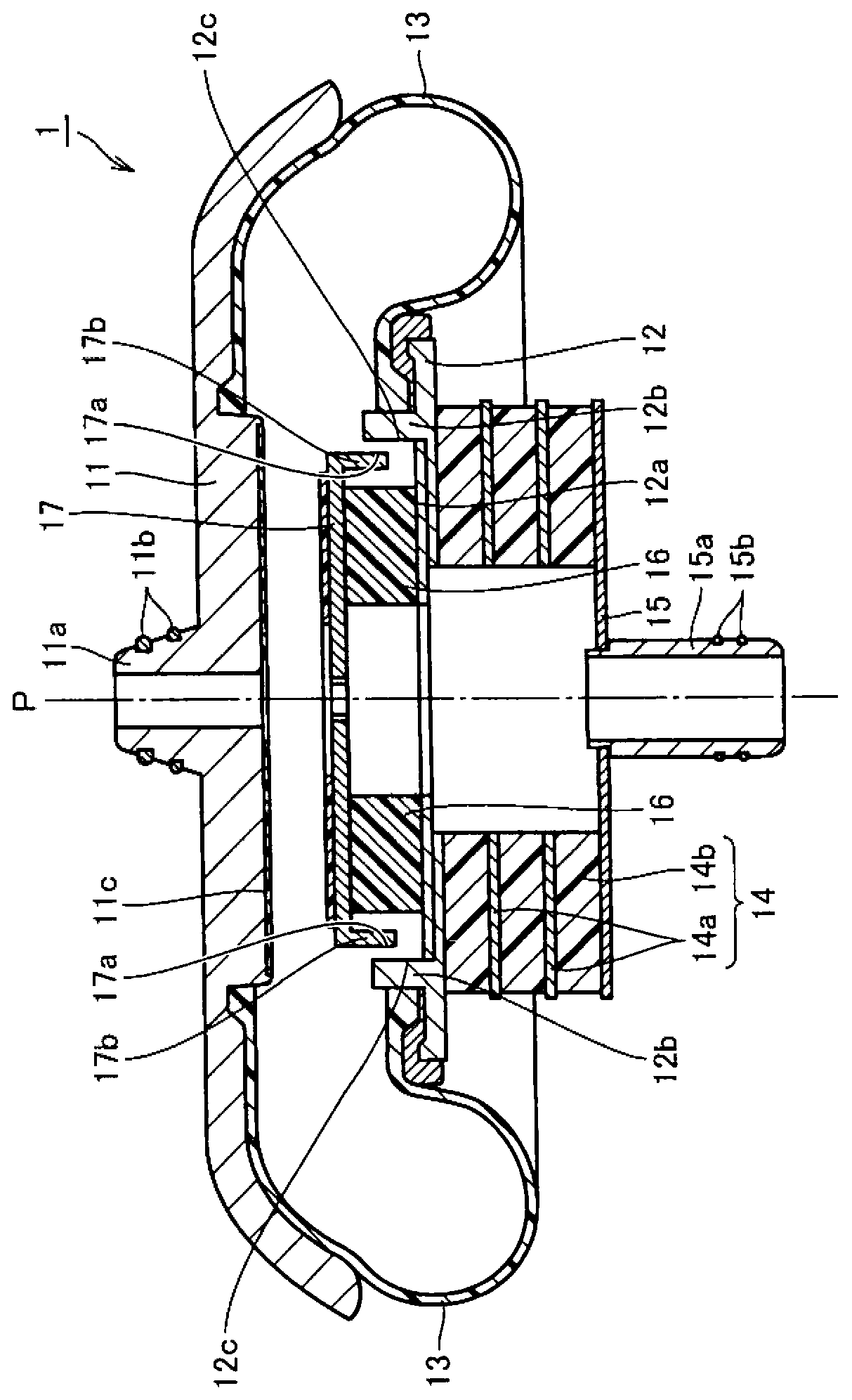
[0067] First, Embodiment 1 which is one embodiment of the present invention will be described. First, the structure of the air spring 1 of the present embodiment will be described. refer to figure 1 , The air spring 1 mainly has: the outer cylinder 11 as the first support member, the lower panel 12 as the second support member, the diaphragm 13, the outer stopper 14, the rubber lower plate 15 as the third support member, the built-in stopper member 16, and a stopper member 17 as a fourth supporting member.

[0068] In a region including the axis (central axis) P of the outer tube 11 , a vehicle body side coupling 11 a protruding along the axis P toward the side opposite to the side of the lower panel 12 is formed. An O-ring 11b is attached to the outer peripheral portion of the vehicle body side coupling 11a. The outer cylinder 11 is connected to a vehicle body side (not shown) via a vehicle body side coupling 11 a.

[0069] The lower panel 12 is arranged so as to share t...

Embodiment approach 2

[0085] Next, Embodiment 2 which is another embodiment of the present invention will be described. The air spring 2 of the present embodiment basically has the same structure as the air spring 1 of the above-described first embodiment, and achieves the same effect. However, the air spring 2 of the present embodiment is different from the air spring 1 of the first embodiment in terms of the structure of the stopper member and the guide portion.

[0086] refer to Figure 5 , in the air spring 2, like the air spring 1, a guide portion 22b is formed on the second opposing surface 22a of the lower panel 22 facing the outer cylinder 21, and the guide portion 22b protrudes in the direction along the main load direction. , opposite to the stop member 27 in a direction perpendicular to the main load direction. Here, in this embodiment, the guide part 22b is formed on the 2nd opposing surface 22a so that it may oppose the inner peripheral surface of the stopper member 27. As shown in F...


PUM


Abstract

The present invention provides an air spring which improves buffer performance in air discharging through effectively performing elasticity of a stopper component. The air spring (1) is provided with the following components: an outer cylinder (11), a lower panel (12), a diagram (13), a rubber lower board (15), a built-in stopper component (16), and a stopper component metal part (17). A second opposing surface (12a) of the lower panel (12), which opposes the outer cylinder (11), is provided with a guiding part (12b). The guiding part (12b) is projected in the main load direction and opposes the stopper component metal part (17) in a direction that is vertical to the main load direction. At least one surface in a stopper component outer surface (17a) of the stopper component metal part (17), which opposes the guiding part (12b), and a guiding part inner surface (12c) of the guiding part (12b), which opposes the stopper component metal part (17), has reduced dynamic friction coefficient.

Description

technical field [0001] The present invention relates to an air spring, and more specifically, relates to an air spring capable of improving cushioning performance during deflation by effectively exerting the elasticity of a stopper member. Background technique [0002] In railway vehicles and the like, air springs are arranged between the vehicle body and the bogie in order to reduce the shock and vibration received by the vehicle body during running. As an air spring, see Figure 8 and Figure 9 , a well-known beamless air spring 100, which mainly has: an outer cylinder 110; a lower panel 120 disposed below the outer cylinder; a rubber diaphragm 130 configured to connect the outer cylinder 110 and the lower panel 120; Laminated rubber 140 below 120 ; and Laminated rubber lower plate 150 below laminated rubber 140 . In addition, for the purpose of ensuring good cushioning performance in a deflated state such as a burst state, an air spring in which a stopper member made of...

Claims


Application Information

Patent Timeline
Patent Type & Authority Applications(China)
IPC IPC(8): F16F9/05
Inventor 泽隆之
Owner SUMITOMO ELECTRIC IND LTD
Why Eureka
Try Eureka