Magnetic antitheft valve

A magnetic and valve technology, which is applied in the direction of valve details, valve devices, devices to prevent accidental or unauthorized actions, etc., can solve the problems of inability to overcome spring resistance, susceptibility to sand and dust, low mechanical strength, etc., to eliminate valves Unable to work, easy to process and assemble, good effect of implementation

Inactive Publication Date: 2013-05-01
ANHUI TONGLING KELI VALVE
View PDF14 Cites 3 Cited by
  • Summary
  • Abstract
  • Description
  • Claims
  • Application Information

AI Technical Summary

Problems solved by technology

Chinese patent CN200520068586.1 discloses a structure in which magnetic pins are installed on the side wall. However, when machining holes on the side wall, not only is it difficult to clamp, but the machining accuracy is limited; moreover, there are holes left on the side wall, which are exposed to sand in the wild. Dust, rain damage, and sometimes man-made damage, but it does not play a substantial role
There are many similar structures, but such structures have the following defects: First, after a long time, the spring coefficient of the spring is easy to change and become invalid; second, the magnet material is relatively brittle, with low mechanical strength, improper operation or long The use of time will also cause the magnet to break, causing the locking mechanism to fail; the third is that the key is mainly used to overcome the resistance of the spring, because two magnets are used to overcome the resistance of the spring to realize unlocking after their magnetic repulsion, but because the key is kept Improper, resulting in weakened magnetism, unable to overcome the spring resistance, and eventually lead to unlocking failure sometimes occurs

Method used


Image

  • Magnetic antitheft valve
  • Magnetic antitheft valve
  • Magnetic antitheft valve

Examples


Embodiment Construction

[0031] The content of the present invention will be described below in conjunction with specific embodiments.

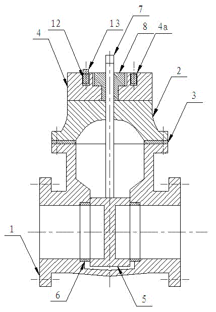
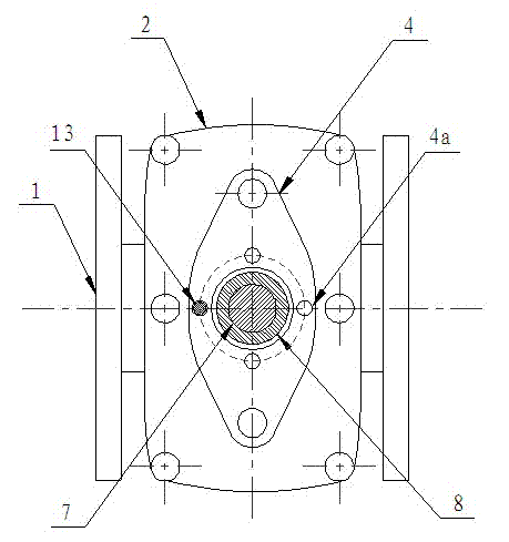
[0032] Such as figure 1 As shown, it is the front view of the magnetic anti-theft valve of the present invention, figure 2 for its top view. The magnetic anti-theft valve of the present invention comprises: a valve body 1, a valve cover 2, a valve body sealing ring 3, a valve cap 4, a valve plate 5, a valve plate sealing ring 6, a valve stem 7, a T-shaped piece 8, and a gland 9. The inside of the valve body 1 is provided with a larger cavity, and there are open openings at both ends, which facilitates the entry and exit of fluid. The valve cover 2 is installed above the valve body 1 , and a certain cavity is provided inside the valve cover 2 , and the cavity matches the cavity inside the valve body 1 . A valve body sealing ring 3 is provided between the valve cover 2 and the valve body 1 to prevent fluid leakage, and the three are tightly locked together by a loc...


PUM


Abstract

The invention relates to a magnetic antitheft valve, which comprises a valve rod and also comprises a valve cap, a press cover and a key, wherein a valve cap groove is uniformly distributed in the upper end surface of the valve cap, a pin and a first permanent magnet are arranged in the valve cap groove. A valve rod matching element is arranged in the press cover, a valve rod matching groove and a groove are arranged in the lower end surface of the valve rod matching element, a first blind hole groove and a second blind hole groove are symmetrically distributed in the upper end surface of the press cover, a second permanent magnet is embedded in the key, and the magnetism of the second permanent magnet is greater than that of the first permanent magnet. The magnetic antitheft valve provided by the invention can be in a split structure, the part processing and assembly can be convenient, the maintenance cost is low in the use process, and only corresponding damaged parts need to be replaced. A spring of the existing magnetic valve is omitted, and the problem that the valve cannot work because of the spring failure is avoided. The guarding and maintenance by specially-assigned persons is not needed, the use is convenient, the magnetic antitheft valve is very suitable for being installed and used in occasions including residential subdistricts, outdoors and the like, and the implementation effect is good.

Description

technical field [0001] The invention relates to a valve, in particular to an anti-theft valve, which uses a magnetic tool to unlock. Background technique [0002] Valves are key control components in fluid delivery systems, with functions such as cut-off, regulation, flow diversion, reverse flow prevention, pressure stabilization, flow diversion, or overflow and pressure relief. Valves used in fluid control systems range from the simplest cut-off valves to various valves used in extremely complex automatic control systems, with a wide variety of varieties and specifications. Valves can be used to control the flow of various types of fluids such as air, water, steam, various corrosive media, mud, oil, liquid metal and radioactive media. [0003] In the existing valve structure, the rotation of the hand wheel generally drives the valve plate to move up and down, so as to realize the closing or opening of the valve. However, many of such valves are installed in living quarter...

Claims


Application Information

Patent Timeline
Patent Type & Authority Applications(China)
IPC IPC(8): F16K35/16
Inventor 汪军平
Owner ANHUI TONGLING KELI VALVE
Why Eureka
Try Eureka