Singularity margin detection method based on screw space included angle for serial and parallel robot mechanisms

A space angle and robot technology, applied in the direction of instruments, special data processing applications, electrical digital data processing, etc., can solve problems such as lack of coordinate invariance, singularity margin index lacks geometric or physical meaning, etc., to improve calculation efficiency Effect

Inactive Publication Date: 2013-05-01
TONGJI UNIV
View PDF3 Cites 5 Cited by
  • Summary
  • Abstract
  • Description
  • Claims
  • Application Information

AI Technical Summary

Problems solved by technology

These methods often require the help of optimization algorithms with a large amount of calculation, and the singular margin indicators proposed in some methods lack the necessary geometric or physical meaning, and do not have coordinate invariance

Method used


Image

  • Singularity margin detection method based on screw space included angle for serial and parallel robot mechanisms
  • Singularity margin detection method based on screw space included angle for serial and parallel robot mechanisms
  • Singularity margin detection method based on screw space included angle for serial and parallel robot mechanisms

Examples


Embodiment 1

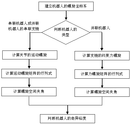
[0045] Embodiment 1: The present invention will be further described below in conjunction with a 3R planar robot. For the flow chart of robot singularity margin detection, see figure 1 shown, including the following key steps:

[0046] (1) Establish the spiral coordinate system of the robot;

[0047] (2) Calculate the joint motion spiral and form a spiral matrix;

[0048] (3) Calculate the determinant of the N-order extended spiral matrix;

[0049] (4) Calculate the determinant of the N-1 order extended spiral matrix;

[0050] (5) Calculate the included angle of the spiral space;

[0051] (6) Calculate the singularity margin of the robot.

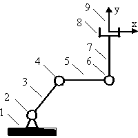
[0052] by figure 2 The 3R planar robot mechanism is shown as an example. The 3R planar robot has 3 revolving pairs, the length of the 3 connecting rods is 0.5m, the angle between the No. 1 connecting rod and the horizontal line is 45°, the angle between the No. 2 connecting rod and the horizontal line is 0°, and the The angle betwe...

Embodiment 2

[0063] Embodiment 2: The present invention will be further described below in conjunction with the 3-UPU parallel robot. For the flow chart of robot singularity margin detection, see figure 1 shown, including the following key steps:

[0064] (1) Establish the spiral coordinate system of the robot;

[0065] (2) Calculate the joint motion spiral and form a spiral matrix;

[0066] (3) Calculate the determinant of the N-order extended spiral matrix;

[0067] (4) Calculate the determinant of the N-1 order extended spiral matrix;

[0068] (5) Calculate the included angle of the spiral space;

[0069] (6) Calculate the singularity margin of the robot.

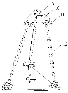
[0070] by figure 2 The 3-UPU parallel robot mechanism is shown as an example. The dynamic platform 10 of the 3-UPU parallel robot is connected to the base through three branch chains, and each branch chain is composed of two universal pairs 11 and one moving pair 12, where the moving pair is a driving joint. The three univer...


PUM


Abstract

The invention relates to a singularity margin detection method based on a screw space included angle for serial and parallel robot mechanisms. The method comprises the following steps of: on the basis of establishing a robot screw coordinate system and calculating a joint kinematic screw or a branched chain restraining force screw, calculating a determinant of an extension screw matrix, and further expressing the screw space included angle; if the screw space included angle is approximately 90 degrees in a moving process of a robot, considering that the singularity margin of the robot is very small; and if the screw space included angle is approximately zero degree, considering that the singularity margin of the robot is very large. The method is characterized in that: an optimization algorithm is not required, so that the method has a high computational efficiency; the screw space included angle is taken as a singularity margin index, which has a geometric meaning; and the method is suitable for detecting the motion singularity margins of serial robots or serial branched chains, and is suitable for detecting the static singularity margins of parallel robots.

Description

technical field [0001] The invention relates to a singularity margin detection method of a serial or parallel robot mechanism based on a spiral space angle. Background technique [0002] Singular configurations have a great influence on the kinematics and dynamics of series and parallel robots, and can be divided into two categories: kinematic singularity and static singularity. If the robot mechanism enters the kinematic singular configuration, it will not be possible to obtain the joint velocity of the series branch chain by specifying the speed of the end effector or the moving platform; if the parallel robot enters the static singular configuration, the branch chain will not be able to provide the necessary binding force. A serial or parallel robot in a singular state will be uncontrollable and even damage the structure of the robot. The singularity margin represents the margin from the robot's current configuration to the singular configuration. Therefore, detecting ...

Claims


Application Information

Patent Timeline
IPC IPC(8): G06F19/00
Inventor 卜王辉陈茂林李梦如
Owner TONGJI UNIV
Why Eureka
Try Eureka