Blanking die structure

A technology for blanking molds and mold bases, applied in forming tools, manufacturing tools, metal processing equipment, etc., to achieve the effects of improving blanking efficiency and finished product quality, smooth feeding, and good practicability

Active Publication Date: 2015-05-06
KUNSHAN XINHONG ENTERPRISE MACHINERY MFG +1
View PDF6 Cites 0 Cited by
  • Summary
  • Abstract
  • Description
  • Claims
  • Application Information

AI Technical Summary

Problems solved by technology

[0004] It is not difficult to see from the above comparative documents that the existing stamping blanking die has structural defects, so it is still necessary to further improve the whole structure of the stamping blanking die to realize automatic feeding and reduce the amount of waste

Method used


Image

  • Blanking die structure
  • Blanking die structure
  • Blanking die structure

Examples


Embodiment Construction

[0012] The present invention will be further described below in conjunction with the accompanying drawings and embodiments.

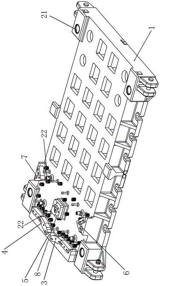
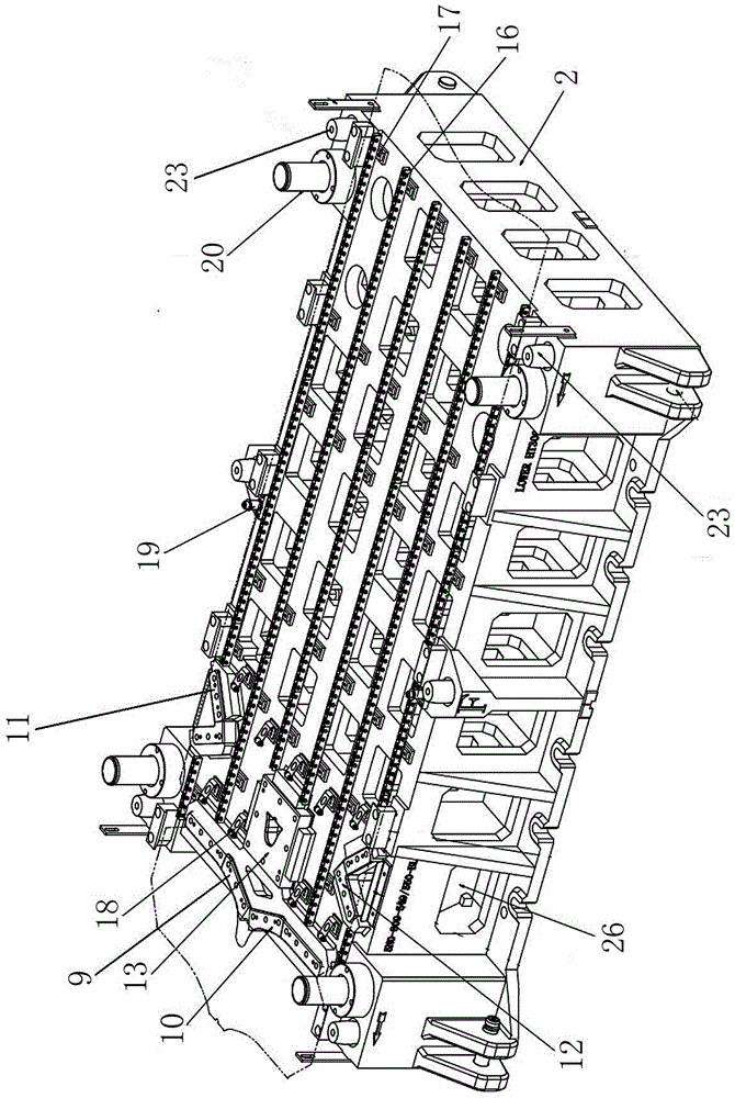
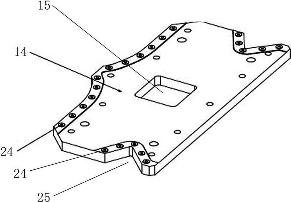
[0013] The invention discloses a blanking die structure, which includes an upper mold base 1 and a lower mold base 2, which is different from the prior art in that two symmetrically distributed The first upper knife block 3 and the second upper knife block 4, the first upper knife block 3 and the second upper knife block 4 form a space 5, and the inner edges of the first upper knife block 3 and the second upper knife block 4 form an arc surface , both sides of the lower surface of the upper mold base 1 are respectively provided with a third upper knife block 6 and a fourth upper knife block 7, the third upper knife block 6 and the fourth upper knife block 7 are in a triangular shape, and the third upper knife block 7 The knife block 6 and the fourth upper knife block 7 are symmetrically distributed, and the upper mold base 1 lower surface between the th...


PUM


Abstract

The invention discloses a blanking die structure which comprises an upper die base and a lower die base. A first upper knife block and a second upper knife block which are symmetrically distributed are arranged at the position, close to the end portion, of the lower surface of the upper die base, an interval is formed between the first upper knife block and the second upper knife block, cambered surfaces are respectively formed on the edges of the inner sides of the first upper knife block and the second upper knife block, and a third upper knife block and a fourth upper knife block are respectively arranged on two sides of the lower surface of the upper die base and are symmetrically distributed. The blanking die is reasonable in whole design, a material conveying mechanism and a floating feed mechanism are arranged on the surface of the lower die base, feeding is smooth, positioning is precise, blanking efficiency and end product quality are effectively improved, and a shock absorption block arranged in the die can effectively reduce noise and shock, prolong service life of the die. The die can simultaneously achieve material breaking, corner cutting and punching and has a good practical applicability. Compared with the prior art, the blanking die structure has outstanding substantive features and progress.

Description

technical field [0001] The invention relates to the technical field of blanking dies, in particular to a blanking and punching die structure for sheet metal parts, and in particular to its mechanical structure. Background technique [0002] Comparative document 1, patent number: CN201120146105.X, application date: 2011.05.10, patentee: Shenyang Laijin Auto Parts Co., Ltd. This case discloses "a blanking die", which is characterized in that: it consists of an upper die and The lower mold is composed of: the upper mold is: guide sleeves are installed at both ends of the upper mold base, a material-returning polyurethane plate is arranged between the upper mold base and the upper mold bottom plate, and a punching punch and a blanking die insert are installed under the upper mold bottom plate ; The lower mold is: the lower mold base and the lower mold bottom plate are supported by a steel frame, the blanking punch insert and the punching die are installed on the lower mold base,...

Claims


Application Information

Patent Timeline
Patent Type & Authority Patents(China)
IPC IPC(8): B21D37/10
Inventor 徐洪泉
Owner KUNSHAN XINHONG ENTERPRISE MACHINERY MFG
Why Eureka
Try Eureka