
Elevator with vibration damper

A vibration damping device and elevator technology, applied in the field of elevators, can solve the problems of large-scale hoist, increased sheave width, and reduced service life of slings, etc., and achieve the effects of reducing load tension, reducing width and improving service life

Inactive Publication Date: 2013-05-08
HITACHI LTD
View PDF5 Cites 15 Cited by
  • Summary
  • Abstract
  • Description
  • Claims
  • Application Information

AI Technical Summary

Problems solved by technology

In this way, the service life of the sling may be reduced due to the increased tension of the sling
In addition, the method of increasing the number of slings can also be adopted, but this method has the problem that the width of the sheave will increase and the size of the hoist will increase.

Method used


Image

  • Elevator with vibration damper
  • Elevator with vibration damper
  • Elevator with vibration damper

Examples


Embodiment Construction

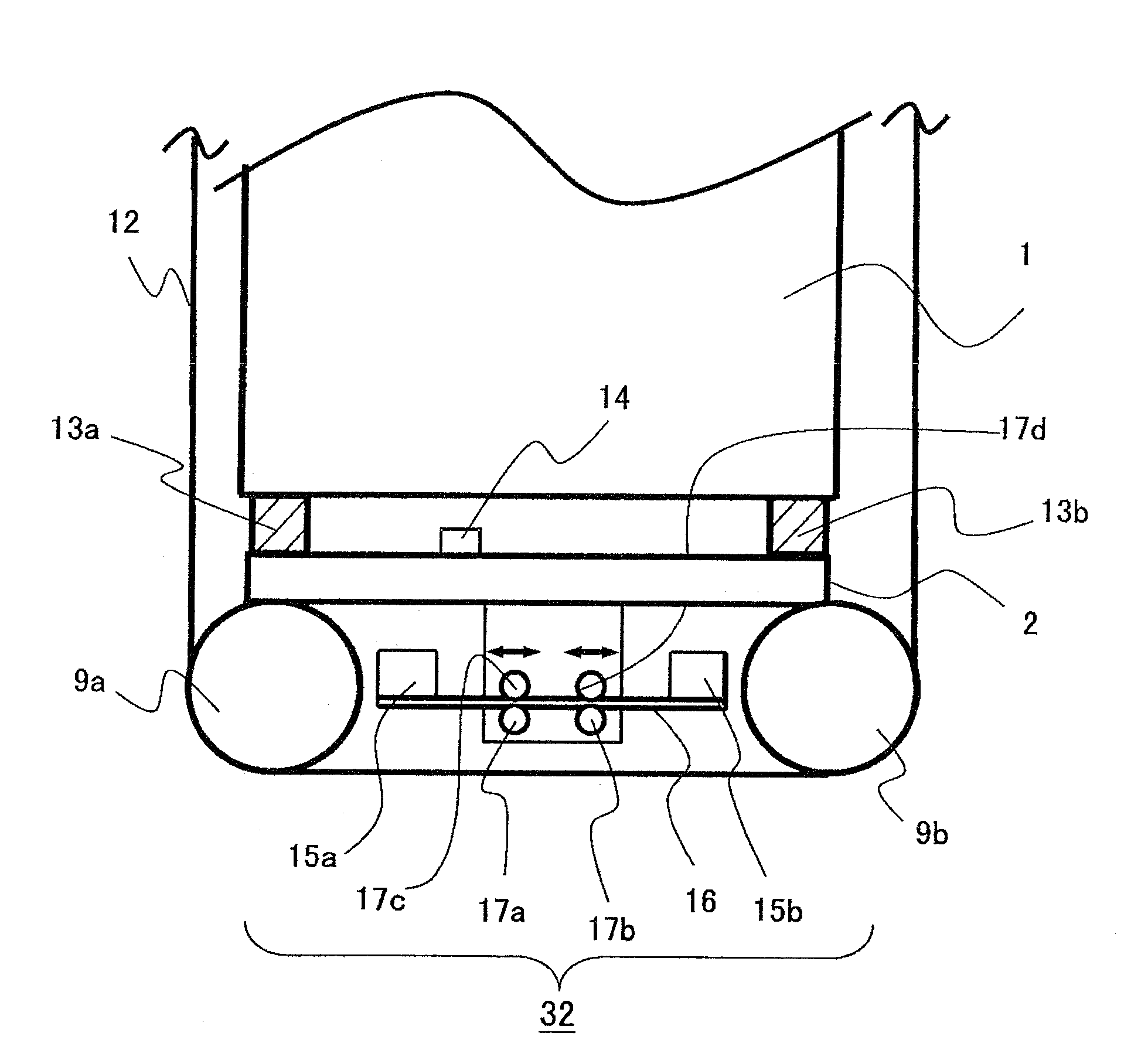
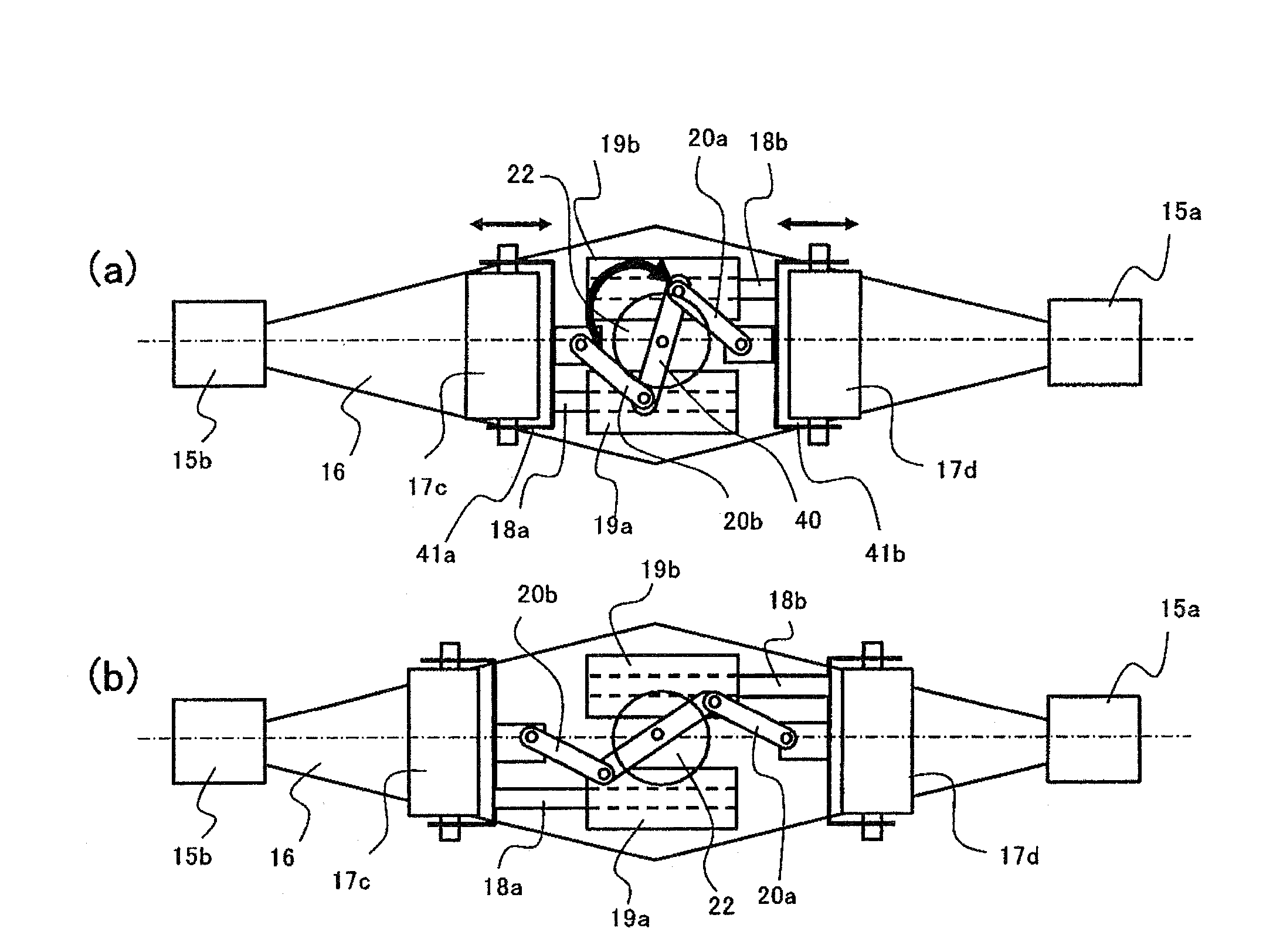
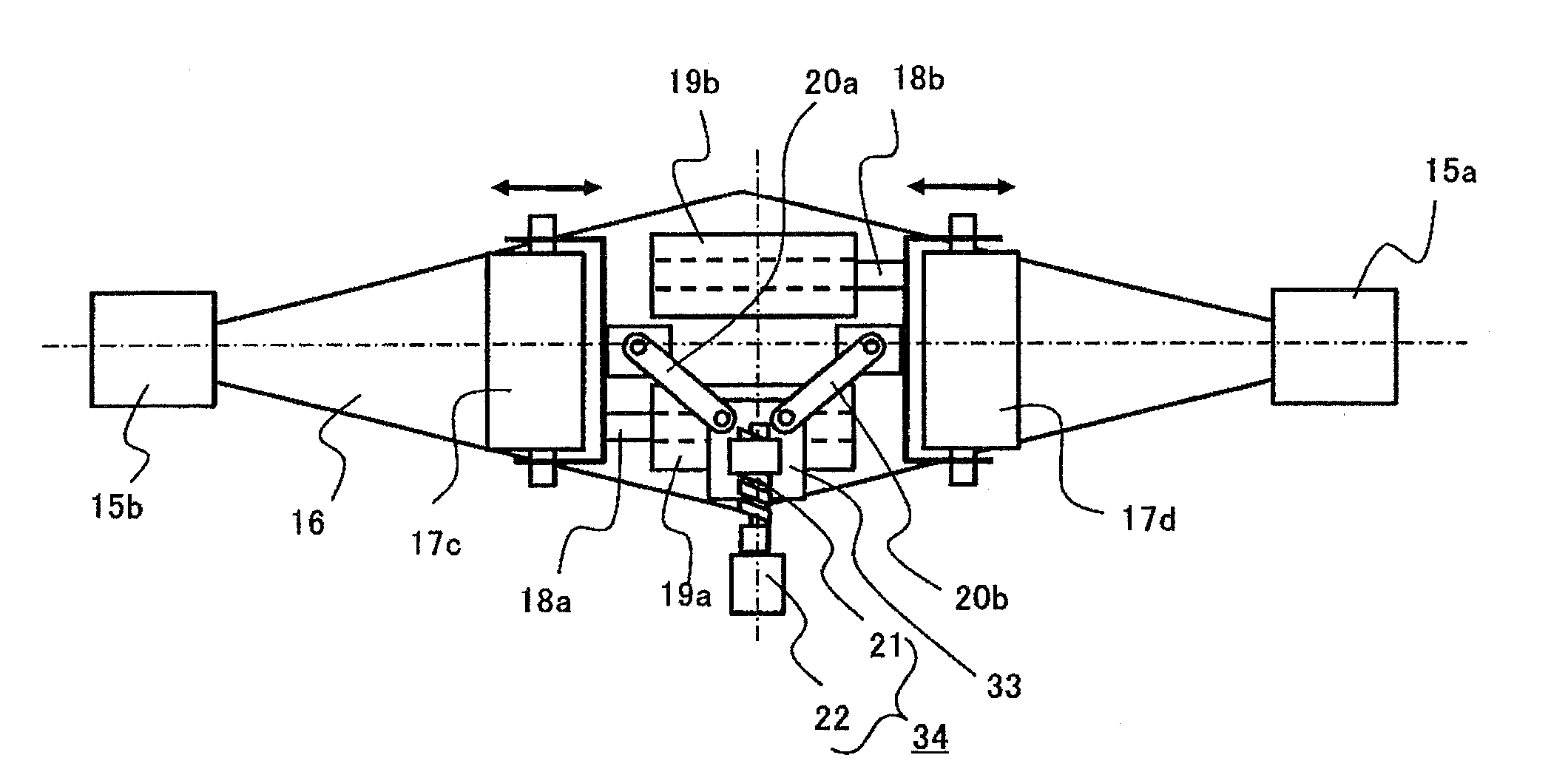
[0066] Refer to the following Figure 1 to Figure 6 The structure, function and effect of the vibration damping device in the elevator according to the first to fourth embodiments of the present invention will be described. Before describing the damping device in the first to fourth embodiments of the present invention, first refer to Figure 7 An overall structure of a dynamic damper in an elevator including the prior art which is the premise of the present invention will be described.

[0067] exist Figure 7 Among them, 1 means the car room, 2 means the car frame, 3 means the balance weight, 4 means the hoist, 5 means the rope pulley, 6a, 6b means the pulley, 7a, 7b means the spring at the end of the sling, 8 means the balance weight pulley, 9a , 9b represent the lower pulley of the car, 10a, 10b represent the spring of the dynamic shock absorber, 11 represent the weight of the dynamic shock absorber, 12 represent the main sling, 13 represent the anti-vibration rubber und...


PUM


Abstract

An elevator with a vibration damper is disclosed. A dynamic vibration absorber (32) is disposed on the lower part of an elevator car (1) and is used for reducing vertical vibration inside the elevator car. The dynamic vibration absorber is provided with an elastic component (16), counter weights (15) disposed on two ends of the elastic component, a single drive unit for altering gaps between a fulcrum of the elastic component and each counter weight, a sensor (14) for detecting a load capacity of the elevator car, and a detection unit for detecting positions and speed of the elevator car. The single drive unit alters and controls the gaps between the fulcrum and the counter weights, so as to enable an anti-resonance point to accord with shock excitation vibrational frequency to the elevator car in an elevator car vibration system, wherein the anti-resonance point changes with the changes of positions and load capacities of the elevator car, and the shock excitation vibrational frequency changes with the changes of the speed of the elevator car. Moreover, two sides of the central part of the elastic component is respectively provided with a pair of rollers (17) which clamp the elastic component from up and down, and the fulcrum of the elastic component is formed by the positions of the rollers.

Description

technical field [0001] The invention relates to an elevator with a vibration damping device for reducing vibrations in the elevator car. Background technique [0002] The elevator car is connected to a counterweight that balances approximately half of the load of the elevator car through a sling, and the elevator car is moved up and down by hoisting the sling. In recent years, elevators without a machine room, in which the hoist is installed in the hoistway, have gradually become mainstream. In elevators without a machine room, in order to realize the miniaturization of the hoist, the so-called 2:1 rope winding method is adopted in which the amount of winding of the hoist is twice the amount of movement of the elevator car. In this 2:1 rope winding method, the total length of the rope is about twice that of the 1:1 rope winding method in which the movement amount of the elevator car is equal to the rope winding amount of the hoist. [0003] When an elevator with long ropes...

Claims


Application Information

Patent Timeline
IPC IPC(8): B66B11/02
Inventor 野口直昭小笠原刚河村阳右
Owner HITACHI LTD
Learn More