Injection method for static sounding probe rod

A probe rod and penetration technology, which is applied in the field of foundation soil survey, construction, infrastructure engineering, etc., can solve the problems of time-consuming, labor-intensive, labor-intensive, etc., and achieve the effect of improving the verticality of the probe rod and reducing the work intensity.

Active Publication Date: 2013-05-08
SHANGHAI GEOTECHN INVESTIGATIONS & DESIGN INST
View PDF6 Cites 9 Cited by
  • Summary
  • Abstract
  • Description
  • Claims
  • Application Information

AI Technical Summary

Problems solved by technology

This test operation method is labor-inte

Method used


Image

  • Injection method for static sounding probe rod
  • Injection method for static sounding probe rod
  • Injection method for static sounding probe rod

Examples


Embodiment 1

[0032] Embodiment one: if Figure 5 As shown, two kinds of probe rods with different diameters are used for combination. The front part of 20m-25m uses a 36mm diameter probe rod, and the latter part uses a 40mm or 42mm diameter probe rod. This combination method can effectively ensure the rigidity of the probe rod. It will not break easily when penetrating.

[0033] Before the start of construction, the straightness of each probe rod can be inspected, generally by visual method. In the case of high precision requirements, the probe rod is leaned against the inner side of the angle steel with high straightness and passed the visual inspection while rotating. Straightness of the probe rod.

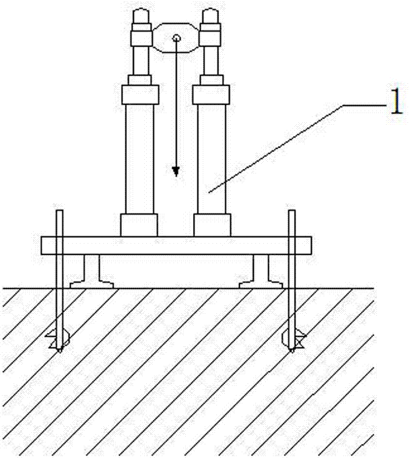
[0034] Such as image 3 As shown, the preparatory work before penetration: Arrange enough ground anchors of drilling rig 1, level the body of the drilling rig so that its outriggers are in full contact with the ground, and use a spirit level to check the levelness. Check the verticality o...

Embodiment 2

[0044] Embodiment 2: The method of this embodiment is basically the same as that of Embodiment 1. The difference is that a 15-20m protective pipe is used to press into the protection probe rod, which is suitable for soft soil layers in the test area and higher penetration depth requirements (for example, greater than 60m).

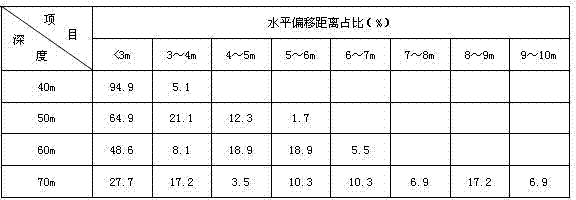
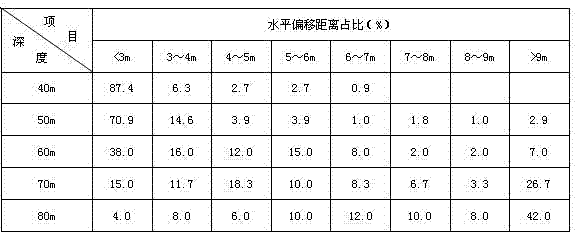
[0045] Such as figure 1 , 2 as shown, figure 1 For adopting the operation method of the present embodiment in the test data of 59 holes in the Chongming country park project in Shanghai; figure 2 In order to adopt the test data of 119 holes operated in the China Expo Convention and Exhibition Complex Project (North Block) in this embodiment, it can be clearly seen from the two figures that the present invention has a significant effect on reducing the inclination when the probe rod penetrates , to increase the test success rate.


PUM


Abstract

The invention belongs to the field of geotechnical engineering investigation in-situ tests and particularly relates to an injection method for a static sounding probe rod. The injection method for the static sounding probe rod is characterized in that after the probe rod is injected into a static sounding hole at an angle smaller than 0.3 degree, injection is stopped every time the probe rod is injected at a center distance. The probe rod conducts clockwise rotation through a pipe wrench. Angle data of a probe is observed. When the trend that the angle data becomes small occurs, rotation and continuous injection of the probe rod is stopped when the angle data is the smallest; and when the trend that the angle data becomes large occurs, the probe rod continues to rotate along the clockwise direction and continues to be injected after returning to an original position. The injection method for the static sounding probe rod has the advantages of improving perpendicularity of the static sounding probe rod, improving the injection depth of the probe rod at one time as much as possible under restriction of permitted inclined degree of the probe rod and without adoption of traditional means of placing the guide protective sleeve downwards to improve the perpendicularity of the of the probe rod and reducing working intensity of static sounding field operation.

Description

technical field [0001] The invention belongs to the field of in-situ testing of geotechnical engineering survey, and in particular relates to a penetration method of a static penetration probe rod. Background technique [0002] Static penetration testing is an in-situ test method commonly used in geotechnical engineering investigation. By pressing a special probe into the soil to measure the penetration resistance of the soil layer, the mechanical parameters of the soil layer that can be used for engineering design are obtained. This in-situ testing method is widely used in engineering investigation. However, due to the inclination of the probe rod during penetration, the probe penetrating into the soil layer will deviate from the vertical line position of the center of the exploration hole on the ground, so that the test data cannot truly reflect the static penetrating index of the vertically downward stratum at the position of the ground. causing the test to fail. Due to...

Claims


Application Information

Patent Timeline
IPC IPC(8): E02D1/00
Inventor 夏群陈琛龚渊张银海周年顺沈超
Owner SHANGHAI GEOTECHN INVESTIGATIONS & DESIGN INST
Why Eureka
Try Eureka