In-pipe water cutter

A technology of hydraulic cutting and cutter, which is applied in the direction of wellbore/well components, earthwork drilling and production, etc. It can solve the problems of tubing damage, inaccurate calculation of charge amount, etc., and achieve smooth fracture, low requirements on job site conditions, and reuse reliable effect

Inactive Publication Date: 2015-09-09
CHINA UNIV OF PETROLEUM (EAST CHINA)
View PDF8 Cites 0 Cited by
  • Summary
  • Abstract
  • Description
  • Claims
  • Application Information

AI Technical Summary

Problems solved by technology

When cutting, the casing and oil pipe are often damaged due to inaccurate calculation of charge amount

Method used


Image

  • In-pipe water cutter
  • In-pipe water cutter
  • In-pipe water cutter

Examples


Embodiment Construction

[0037] The present invention will be further described below in conjunction with accompanying drawing.

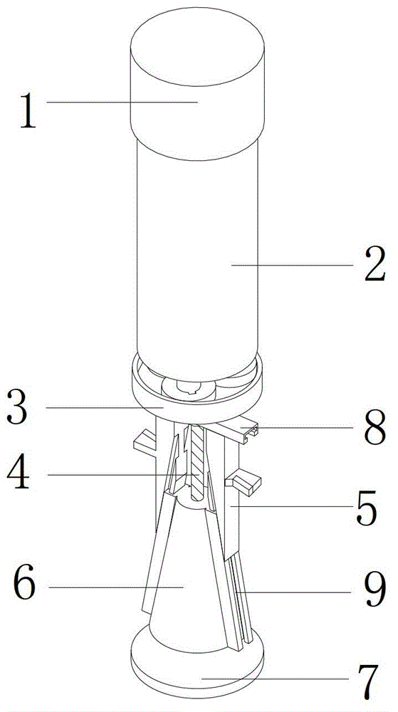
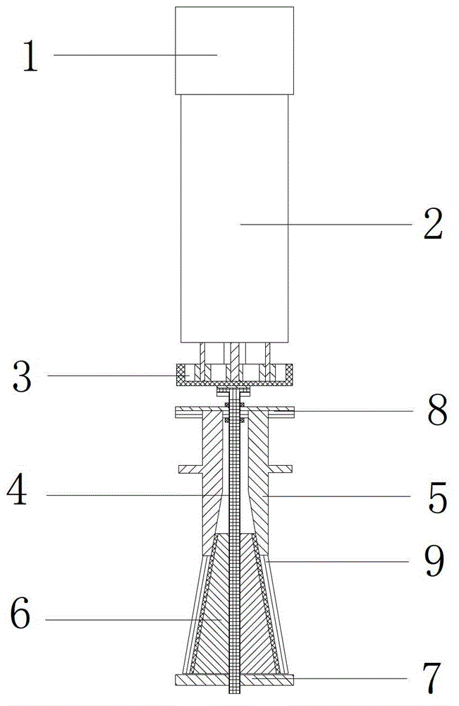
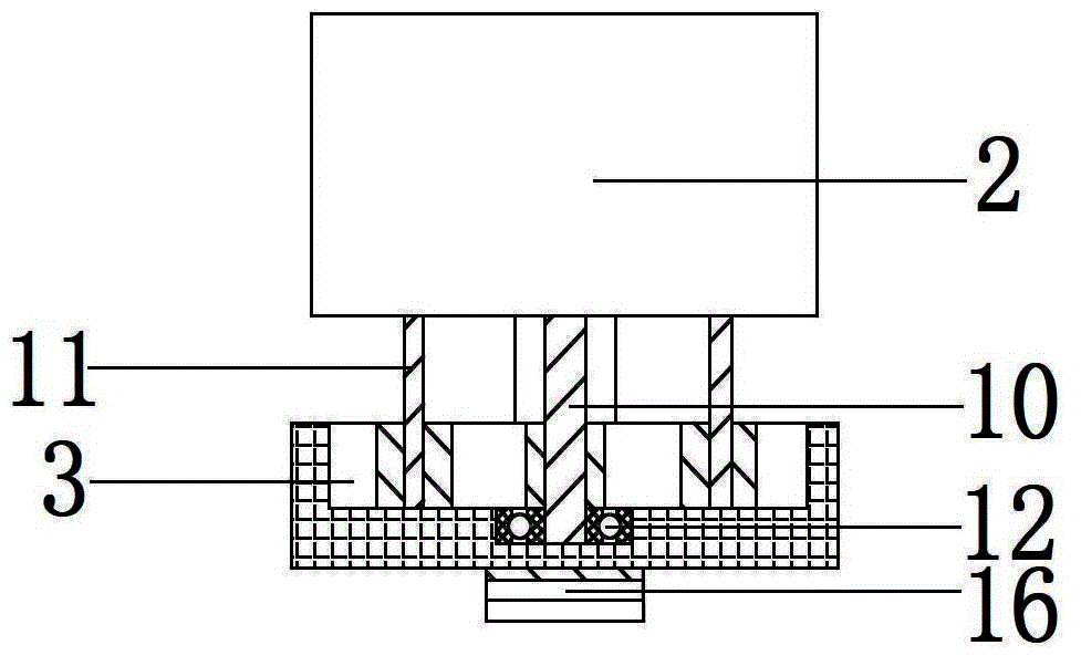
[0038] Such as Figure 1a , Figure 1b As shown, the hydraulic cutter in the pipe includes hydraulic anchor 1, hydraulic motor 2, deceleration and torque increasing device 3, screw rod 4, cutter 5, center lower cone 6, base 7 and guide rail 8; the upper end of hydraulic anchor 1 and the input pipeline connection (not shown in the figure), the lower end is connected to the upper end of the hydraulic motor 2, the hydraulic anchor 1 provides support for the hydraulic cutter in the pipe, and bears the cutting reaction force from the cutter 5 when cutting the pipe body; the lower end of the hydraulic motor 2 is connected to the deceleration The upper part of the torque increasing device 3 is connected, and the hydraulic motor 2 converts the hydraulic energy provided by the wellhead hydraulic pump into mechanical energy to provide power for the hydraulic cutter in the pipe; 3 pl...


PUM


Abstract

The invention belongs to the field of oil exploitation, and particularly relates to a hydraulic cutter in a pipe. When the hydraulic cutter in the pipe cuts small-diameter oil pipe, the hydraulic cutter in the pipe can be directly lowered to a set position of the oil pipe to cut,. Besides, the cutting is controlled by hydraulic pressure at a wellhead, thus operation is simple, safe and reliable, requirement of operation site is low, and no other accidental injuries occur. Meanwhile, when the oil pipe is cut by the hydraulic cutter in the pipe, fracture surfaces are smooth, the oil pipe is not damaged, and the recycle of the oil pipe is provided with reliable guarantee.

Description

technical field [0001] The invention belongs to the field of petroleum exploitation, and in particular relates to an in-pipe hydraulic cutter, and more specifically, relates to a hydraulic cutting tool suitable for cutting inside small-diameter oil pipes of oil production wells in oil fields. Background technique [0002] In recent years, with the rapid development of the petrochemical industry, technological innovations in oil exploration and oil field workover are also changing with each passing day. However, behind the rapid development of high-tech, there are also a series of problems that people have to pay attention to, which cause various engineering accidents. With the continuous deepening of oilfield exploitation, many oilfields have gradually entered the middle and late stage of development, and the deformation, dislocation and jamming of downhole tubing in oilfields all over the country are also increasing year by year. In order to meet the needs of well workover...

Claims


Application Information

Patent Timeline
Patent Type & Authority Patents(China)
IPC IPC(8): E21B29/06
Inventor 李玉坤朱海张峻杜丙国马清明张纪豪
Owner CHINA UNIV OF PETROLEUM (EAST CHINA)
Why Eureka
Try Eureka