Rotary compressor

A technology of rotating compressors and rotors, used in rotary piston machinery, rotary piston pumps, mechanical equipment, etc., can solve the problems of reduced crankshaft reliability, noise, abnormal compressor vibration, etc., and achieve the effect of ensuring reliability.

Active Publication Date: 2013-05-08
MITSUBISHI ELECTRIC CORP
View PDF4 Cites 2 Cited by
  • Summary
  • Abstract
  • Description
  • Claims
  • Application Information

AI Technical Summary

Problems solved by technology

Therefore, the two-cylinder rotary compressor described in Patent Document 1 has problems in that the reliability of the crankshaft is lowered, and abnormal vibration and noise are generated in the compressor.

Method used


Image

  • Rotary compressor
  • Rotary compressor
  • Rotary compressor

Examples


Embodiment approach 1

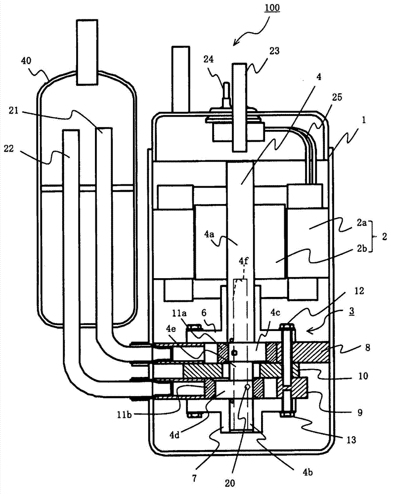
[0018] Figure 1 to Figure 6 is a diagram showing Embodiment 1, figure 1 is a longitudinal sectional view of the twin-cylinder rotary compressor 100, figure 2 and image 3 is a longitudinal sectional view of the compression mechanism part 3 of the two-cylinder rotary compressor 100, Figure 4 yes figure 2 The Z-Z section view in, Figure 5 It is a figure showing the procedure of assembling the first piston 11a to the crankshaft 4 when the relief shape 11a-1 is provided at both axial ends of the inner diameter of the first piston 11a, Figure 6 is a comparison Figure 5 and Figure 7 of the graph ( Figure 6 (a) represents a comparative example, Figure 6 (b) represents this embodiment).

[0019] Below, use Figure 1 to Figure 6 The twin-cylinder rotary compressor 100 according to Embodiment 1 will be described.

[0020] use figure 1 The configuration of the two-cylinder rotary compressor 100 will be described. A motor 2 including a stator 2 a and a rotor 2 b and...

Embodiment approach 2

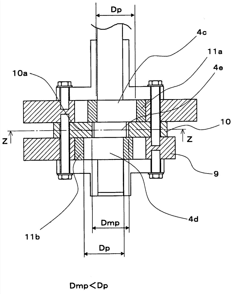
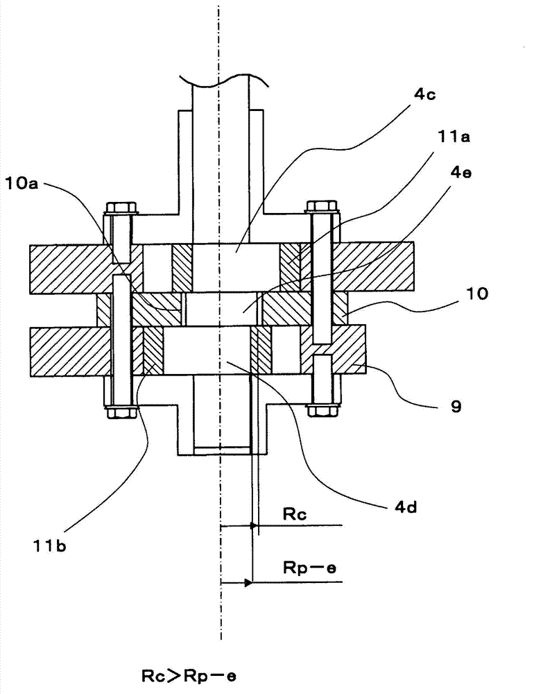
[0080] In Embodiment 1, the relationship between the inner diameter 10 a of the separator 10 and the first piston 11 a and the second piston 11 b is not particularly mentioned. The inner diameter 10 a of the separator 10 and the first piston 11 a and the second piston 11 b may be formed in, for example, the following relationship. In addition, items that are not particularly described in the second embodiment are the same as those in the first embodiment, and the same functions and configurations will be described using the same reference numerals.

[0081] Figure 8 It is a figure which shows Embodiment 2, and is a longitudinal cross-sectional view of the compression mechanism part 3 of the twin-cylinder rotary compressor 100. As shown in FIG.

[0082] Such as Figure 8 As shown, if the distance from the axial center of the intermediate shaft 4e to the inner peripheral surface of the inner diameter 10a of the separator 10 (that is, the radius of the inner diameter 10a of th...


PUM


Abstract

The present invention provides a rotary compressor which can ensure reliability of the crankshaft and realize high output and high efficiency. In a double-cylinder rotary compressor (100), the outer diameter of an intermediate shaft (4e) is formed at a position closer to a periphery side than periphery faces reversed to eccentric sides of a main shaft eccentric part (4c) and a subshaft eccentric shaft (4d),a separating plate (10) is divided into a plurality of parts via sections formed at a through hole of the separating plate (10), and the inner diameter of the through hole of the separating plate (10) is formed to be bigger than the outer diameter of the intermediate shaft (4e) and smaller than the outer diameters of the main shaft eccentric part (4c) and the subshaft eccentric shaft (4d).

Description

technical field [0001] The present invention relates to a rotary compressor for compressing refrigerant gas used in the refrigerating cycle of refrigerating and air-conditioning devices such as air conditioners and refrigerators. Background technique [0002] There are known a multi-cylinder rotary compressor that compresses low-pressure refrigerant gas into high-pressure refrigerant gas by using each of a plurality of compression chambers, and a multi-cylinder rotary compressor that sequentially compresses low-pressure refrigerant gas by using a plurality of compression chambers to generate high-pressure refrigerant. Multistage rotary compressor for gases. In such a compressor having a plurality of compression chambers, the crankshaft includes: a plurality of eccentric portions arranged in the cylinder; and an intermediate shaft provided between adjacent eccentric portions. In addition, in such compressors, the following structure has been proposed in the past: the eccentr...

Claims


Application Information

Patent Timeline
Patent Type & Authority Applications(China)
IPC IPC(8): F04C23/00F04C29/00
CPCF04C18/07F04C18/356F04C23/001F04C23/008F04C29/0021F04C2210/26F04C2240/40Y10S415/00Y10S417/902
Inventor 新井聪经谷真男佐藤幸一
Owner MITSUBISHI ELECTRIC CORP
Why Eureka
Try Eureka