Clutch relay device

A clutch and meshing technology, applied in the direction of transmission device, friction transmission device, belt/chain/gear, etc., can solve the problems of chasing gear tail, dual drive asynchrony, disengagement, etc., to achieve stable engagement state and smooth meshing process. The effect of smooth and smooth transition of the relay process

Active Publication Date: 2013-05-08
CHINA NUCLEAR POWER ENG CO LTD
View PDF9 Cites 10 Cited by
  • Summary
  • Abstract
  • Description
  • Claims
  • Application Information

AI Technical Summary

Problems solved by technology

[0005] If you choose a double-pinion single-rack relay drive, you also need to solve the problem of chasing teeth and tail teeth detachment caused by the asynchronous double drive after the rack and pinion enters the double-drive state

Method used


Image

  • Clutch relay device
  • Clutch relay device
  • Clutch relay device

Examples


Embodiment

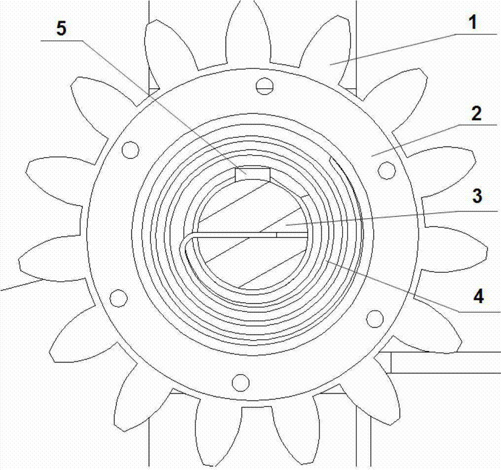
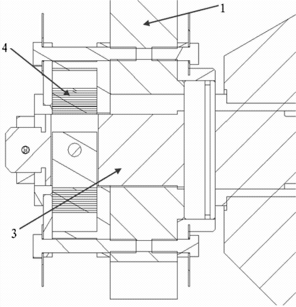
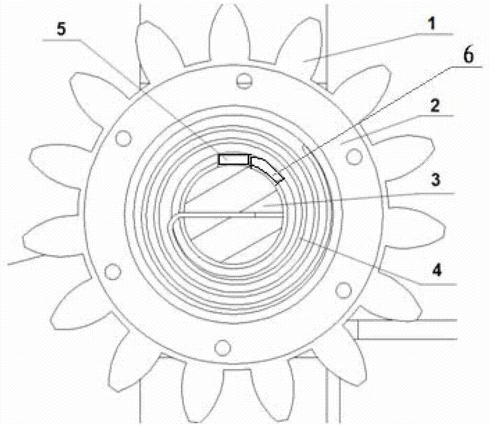
[0030] In this embodiment, the clutch relay device is installed on the lower transmission mechanism of the fuel transfer device (installed on both sides of the reactor building and the fuel building respectively), such as Figure 5 , Figure 6 and Figure 7 As shown, the transmission mechanism transmits the motor torque through the coupling, the bevel gear, and the drive shaft 3. The gear 1 is seated on the rolling bearing of the drive shaft 3 through the connecting sleeve, and the gear 1 meshes with the rack on the transport trolley. , to drive the trolley forward and backward. In the process of relay driving, the rack is driven by one gear in most cases, and only when the transport trolley is about to pass through the fuel transfer channel (two-way), there is a case where one rack contacts two gears at the same time .

[0031] In this embodiment, the working process of the driving transfer device of the clutch relay device can be basically divided into four states, as fol...


PUM


Abstract

The invention discloses a clutch relay device which comprises a driving shaft. A gear is arranged on the driving shaft, a spring box is arranged on the lateral side of the gear, a plane volute spring is arranged between the driving shaft and the spring box, the inner end of the plane volute spring is wound on the driving shaft, and the outer end of the plane volute spring is connected with the spring box. The clutch relay device uses the change of a relative angle between the driving shaft and the gear to achieve the double-clutch effects, solves the problem that a gear and a rack are meshed and demeshsed, solves the problem of collision and interference caused by desynchrony of double motors and guarantees stability of a relay process. The plane volute can achieve overrunning in a certain range, provides a certain range overrunning space, can keep pre-tightening force in an unloaded state and can restore the gear to the normal position.

Description

technical field [0001] The invention relates to the field of double drive relay, in particular to a special clutch relay device in a fuel transfer device. Background technique [0002] During the operation of the pressurized water reactor nuclear power plant, the refueling operation of the reactor shutdown requires the reciprocating transportation of new / spent fuel assemblies between the reactor building and the fuel building. Transport to another factory. Due to the design of the double-layer containment of the third-generation nuclear power plant, the length of the fuel transfer channel has greatly increased compared with the second-generation and second-generation improved nuclear power plants. The lengthening of the transportation path puts forward higher requirements for the transmission system of the fuel transfer device. . [0003] In the process of realizing the above-mentioned transportation of nuclear fuel assemblies, the inventors have found that at least the fo...

Claims


Application Information

Patent Timeline
Patent Type & Authority Applications(China)
IPC IPC(8): F16H35/00
CPCF16H2019/046F16H35/00F16H19/04
Inventor 李建奇杨仲元吴明金青谢亮唐兴贵张鑫李钧王燕刘慧芳孙福江缪岭
Owner CHINA NUCLEAR POWER ENG CO LTD
Why Eureka
Try Eureka